


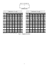
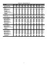
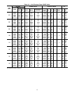
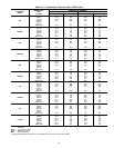
Table 3 — Liquid Line 2 F (1.1 C) Drop in
Saturated Temperature Example
SATURATED
LIQUID
TEMP
PRESSURE
R-134a R-22
F C Psig kPa Psig kPa
100 37.7 124.3 857 195.9 1351
98 36.7 120.1 828 190.2 1311
⌬ PRESSURE 4.2 29 5.7 40
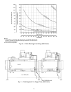
Discharge lines should be looped above the compressors
to avoid having charge flowing back to the oil separator and
compressor during unit shutdown. Wrap back-pressure valve
when brazing discharge line to avoid damaging the valve.
It is recommended that field-supplied pressure relief valves
be installed in each discharge line. Most local codes require
that the relief valves be vented directly to the outdoors. The
vent must not be smaller than the relief valve outlet, and the
pressure setting should be 320 psig (2205 kPa).
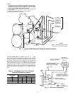
Run a field-supplied
1
⁄
4
-in. (6.4 mm) copper line between
the back-pressure valve on the oil separator (bottom pres-
sure vessel) to the fitting on the refrigerant line entering the
economizer port of the compressor to measure oil pressure
differential. See Fig. 11. The back-pressure valve and the fit-
ting on the refrigerant line have a
1
⁄
4
-in. flare fitting for mak-
ing this connection. The flare nut is field supplied.
IMPORTANT: There is a Schrader-type fitting in each
of the two
1
⁄
4
-in. fittings. These Schrader-type fittings
MUST BE REMOVED before running the line.
The 30HXA units are shipped from the factory with a hold-
ing charge of R-134a. Before opening the refrigerant sys-
tem, relieve system pressure and recover system refrigerant
through the charging valve on the cooler.
30HXC CONDENSER CONNECTIONS — The inlet fluid
connection is always the lower of the 2 condenser con-
nections. It is recommended that a screen strainer with a
minimum of 20 mesh be installed ahead of the condenser
inlet to prevent debris from damaging the internal condenser
tubes.
The outlet water connection is the upper connection of
the 2 connections. The condenser has weld couplings to
connect field-supplied piping. Plan the piping arrangement
in accordance with good piping practices and so that the pip-
ing does not cross in front of the condenser head. Use flex-
ible connections on the condenser piping to reduce vibration
transmission. Offset the piping to permit condenser head re-
moval for maintenance purposes. Install pipe hangers where
needed. Make sure no weight or stress is placed on the water
nozzle.
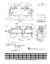
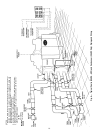
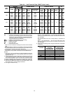
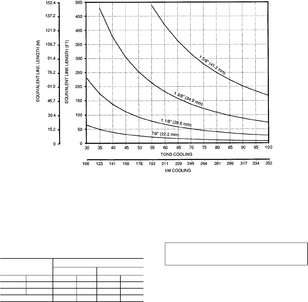
NOTES:
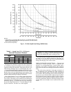
1. Values are for a 2° F pressure drop at 125 F (51.7 C) saturated discharge tem-
perature, 120 F (48.9 C) saturated condensing temperature, and 105 F (40.6 C)
liquid refrigerant temperature.
2. Size each circuit separately.
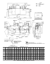
Fig. 9 — R-134a Liquid Line Sizing, 30HXA Units
12