


47
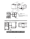
Step 4 — Installing ERV Transitions — When cou-
pling ERV units with Carrier rooftop units an ERV transition is
required to link the ERV unit and the Carrier rooftop unit
together.
ERV UNIT COUPLED WITH A 3 to 12
1
/
2
TON HVAC
UNIT — Complete the following steps to install a transition to
a3to12
1
/
2
ton rooftop unit.
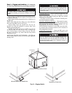
1. Remove the HVAC unit filter door and set aside for later
use.
2. Remove the panel shipped on the HVAC unit covering
the return air chamber. This panel can be discarded.
3. The 62M ERV transition for 3 to 12
1
/
2
ton rooftop units
includes a replacement panel to cover the return opening.
Install the replacement panel, with hood scoop attached,
onto the HVAC unit, over the return air chamber. Screw
in place. The return/exhaust scoop will cover part of the
return air opening in the HVAC unit.
NOTE: The standard transition does not seal tight around the
return air opening on the HVAC unit. This allows for some air
to flow back to the HVAC unit and some to be drawn back
through the ERV unit.
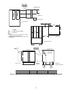
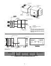
4. Slide the transition between the ERV unit and the HVAC
unit. Refer to Fig. 17-44 to orient the transition. Line up
the transition so that it covers the openings in the HVAC
unit and the ERV unit. The divider in the transition must
separate the supply and return openings in the ERV unit.
Screw the mating flanges of the transition to the ERV unit
through pre-punched holes. Caulk the seams watertight.
Screw the mating flanges on the other side of the transi-
tion to the new return air cover panel on the HVAC unit.
Caulk seams watertight.
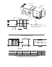
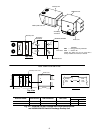
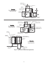
5. On most models the filter access door shipped with the
HVAC unit will be reinstalled above the transition.
6. The transition includes a balancing damper to allow for
the desired separation of the return/exhaust air between
the ERV and HVAC units. This damper has a manual
adjustment. During balancing, this damper will be
adjusted to achieve desired exhaust cfm. The balancing
damper can be accessed through a separate door in the
transition or through the HVAC unit’s filter access door.
See Fig. 17-44.
Step 5 — Make Electrical Connections
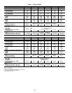
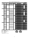
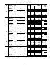
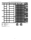
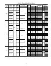
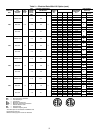
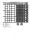
POWER SUPPLY — The electrical characteristics of the
available power supply must agree with the unit nameplate
rating. Supply voltage must be within the limits shown. See
Tables 2 and 3 for electrical and configuration data.
ELECTRICAL CONNECTIONS — The ERV unit must
have its own electrical disconnect box. If the disconnect option
has not been ordered from the factory, it must be field supplied
and installed per local codes. See Tables 2 and 3.
If the ERV unit has an electric pre-heater factory installed, it
will be wired through the ERV unit disconnect.
NOTE: Most ERV units have electrical interlock safety
switches on the access doors, which will not allow the ERV
unit to operate if either of the access doors are opened.
Low Voltage Wiring
— Wire low voltage per diagrams. For
coupled applications, there will be a brown and black wire in
the exhaust chamber, which must be tied into the HVAC unit’s
indoor fan so that when the indoor fan is activated, the ERV
unit will be activated.
48/50TJ, HJ 3 to 12
1
/
2
Ton Rooftop Units with Economizers
— The brown and black wires can be plugged into the econo-
mizer jumper plug on the HVAC unit’s economizer harness.
Insert the brown wire from the ERV unit into terminal 4 in the
jumper plug and insert the black wire from the ERV unit into
terminal 3 in the jumper plug. See Fig. 47.
If the 3 to 12
1
/
2
ton rooftop unit has an economizer in-
stalled, the economizer will have an end switch attached to the
economizer actuator. The end switch must be wired into the
ERV unit as shown in Fig. 48.
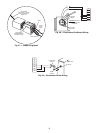
For ERV units coupled with units with factory-installed
economizers, (48/50TM, HJ 15 to 25 ton units 48/50HG, PG 15
to 25 ton units) the ERV transitions to these rooftop units in-
clude an economizer end switch. This switch mounts to the hub
of the economizer damper gear as shown in Fig. 49. Set the end
switch so that the ERV unit’s outside air blower is deactivated
during economizer mode.
For stand-alone units, the ERV unit is jumpered from termi-
nals 6 and 8 and 7 and 9, providing for continuous operation.
The ERV unit should be connected to an on-off device such as
aCO
2
sensor.
High Voltage Wiring (Fig. 50-53)
— Connect high voltage
wiring to the disconnect per Fig. 50, 52 and 53. Check blower
rotation direction and adjust if necessary.
Prior to performing service or maintenance operations on
the ERV unit, turn off and disconnect all power switches to
the unit. Be aware that there may be more than one discon-
nect switch. Electrical shock could cause serious personal
injury or death.
IMPORTANT: Only trained, qualified installers and
service technicians should install, wire, start-up and
service equipment.