57
See Note
See Note
See Note
See Note
See Note
See Note
See Note
See Note
See Note
(OPTIONAL)
(OPTIONAL)
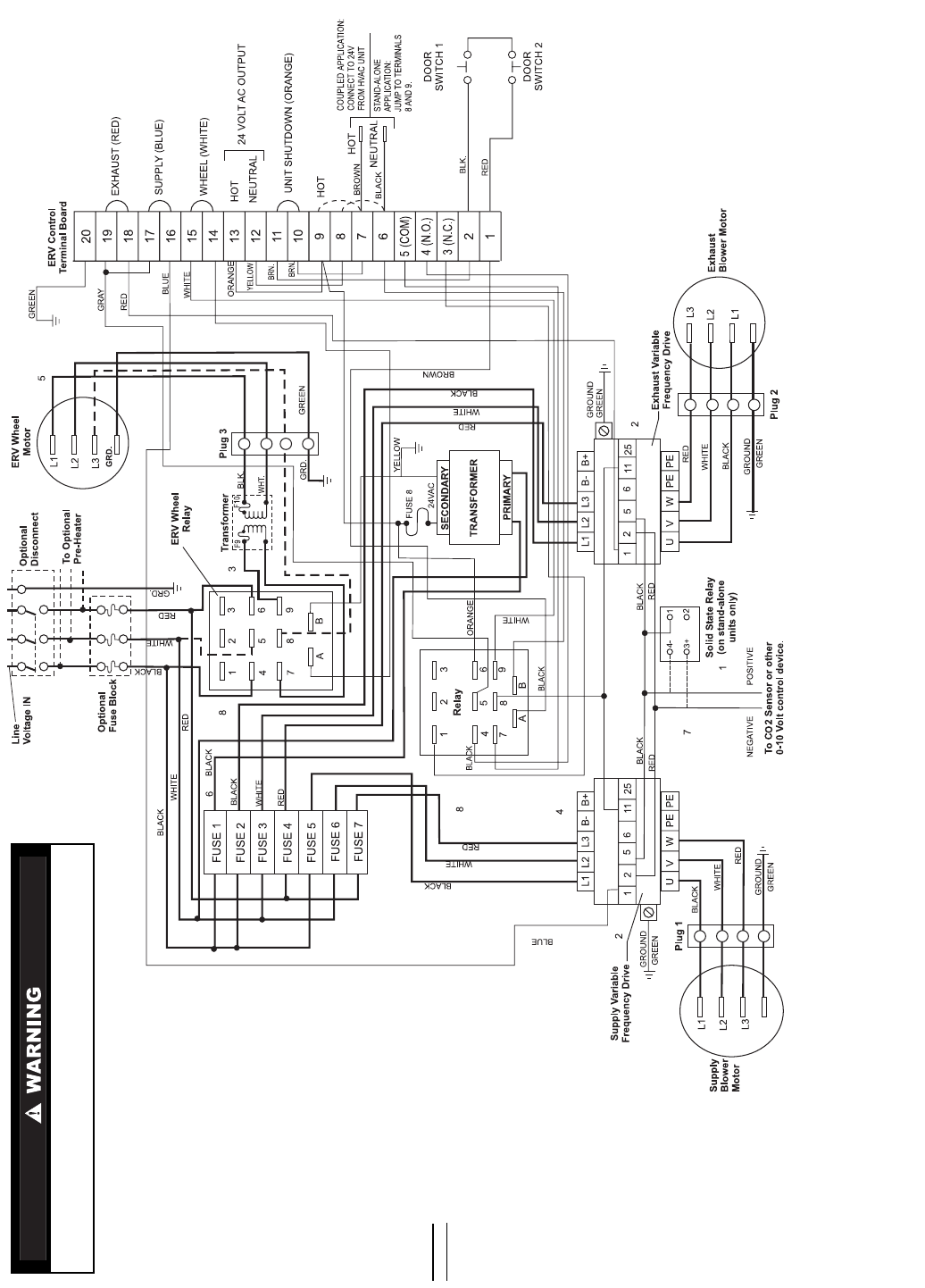
NOTES:
1. When the62M unit isused ina stand-alone application, thesolid-state relay willbe added to activate
ERV at approximately 2 volts. CO
2
sensor output signal is sent to relay. Coupled units are activated
through HVAC unit.
2. Supply and Exhaust Variable Frequency Drive (VFD) terminals no. 25 and no. 2 can be used as a
4 to 20 mA power control source, if desired.
3. Transformer not necessary on all 62M750,950 units.
Before performing service or maintenance operations on 62M unit, turn off power
switches to unit. Multiple switches may exist. Electrical shock could cause personal
injury or death.
4. Variable frequency drives are sensitive to the polarity of a 0 to 10 volt DC control signal. If the control
source is acting properly and the voltage variance can be detected on the proper leads of the VFD,
reverse the leads and the controller will respond.
5. Three-phase motor on all 62M750,950 units.
6. Color determined by primary voltage: Red — 200 vac, Orange — 230 vac, Black — 460 vac.
7. 0 to 10 volt and 4 to 20 mA inputs are polarity sensitive. Reverse leads if signal fails to update controller.
8. DPDT relay may be substituted. If so, pins 2, 5 and 8 will not exist.
LEGEND
WIRING LEGEND
COM — Common
DPDT — Dual Pole, Dual Throw Relay
ERV — Energy Recovery Ventilator
GRD — Ground
NC — Normally Closed
NO — Normally Open
High Voltage
Low Voltage
Fig. 52 — Typical Wiring Schematic, High/Low Voltage with Variable Air Volume Option


