


14
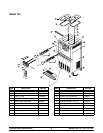
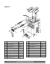
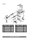
Models 750, 751, 754, 774, 794Important: To the Operator
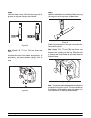
Reset Button
On c ounter models, the reset button is located on the
side of the unit. On console models, the reset button
is located in the service panel. The reset protects the
beater motor from an overloadcondition. If anoverload
occurs, the reset mechanism will trip. To properly reset
the freezer, press the AUTO key to cancel the cycle.
T urn the power switch to the O FF position. Press the
reset button firmly.
Do not use metal objects to press the reset
button. Failure to follow this instruction may
result in electrocution.
T urn the power switch to the ON position. Press the
W ASH key and observe the freezer’s performance.
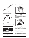
Open the side access panel. Make sure the beater
motor is turning the drive shaft in a clockwise d irection
(from the oper ator end) without binding.
If the beater motor isturning properly,press the WASH
keytocancelt he cycle. Pressthe AUTO key toresume
normal operation. If the freezer shuts down again,
contact a service technician. (For Models 754, 774,
and 794 press the AUTO key on both sides of the unit
to resume normal oper ation.)
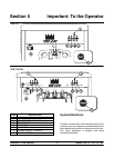
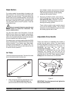
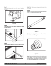
Air Tube
The air tube serves two purposes. One end of the tube
has a hole and the other end does not.
Figure 1
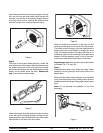
1. After priming the machine, lubricate the o-rings
on the air tube (the end with the hole) and
place it into the m ix inlet hole. E very time the
draw handle is raised, new m ix and air from the
hopper will flow down into the freezing c ylinder.
This will k eep the freezing cylinder pr operly
loaded and will maintain ov errun.
2. During long “No Sale” periods, remove the air
orifice. Lubricate the o-rings on the air tube (the
end without the hole), and place it into the
mix inlet hole. This will prevent any mix f rom
entering the freezing cylinder .
The air or ifice is used t o meter a certain amount
of air into the freezing cylinder . The air orifice
maintains overrun andallows enough mix toenter
the freezing cylinder after a draw.
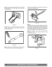
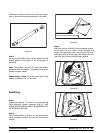
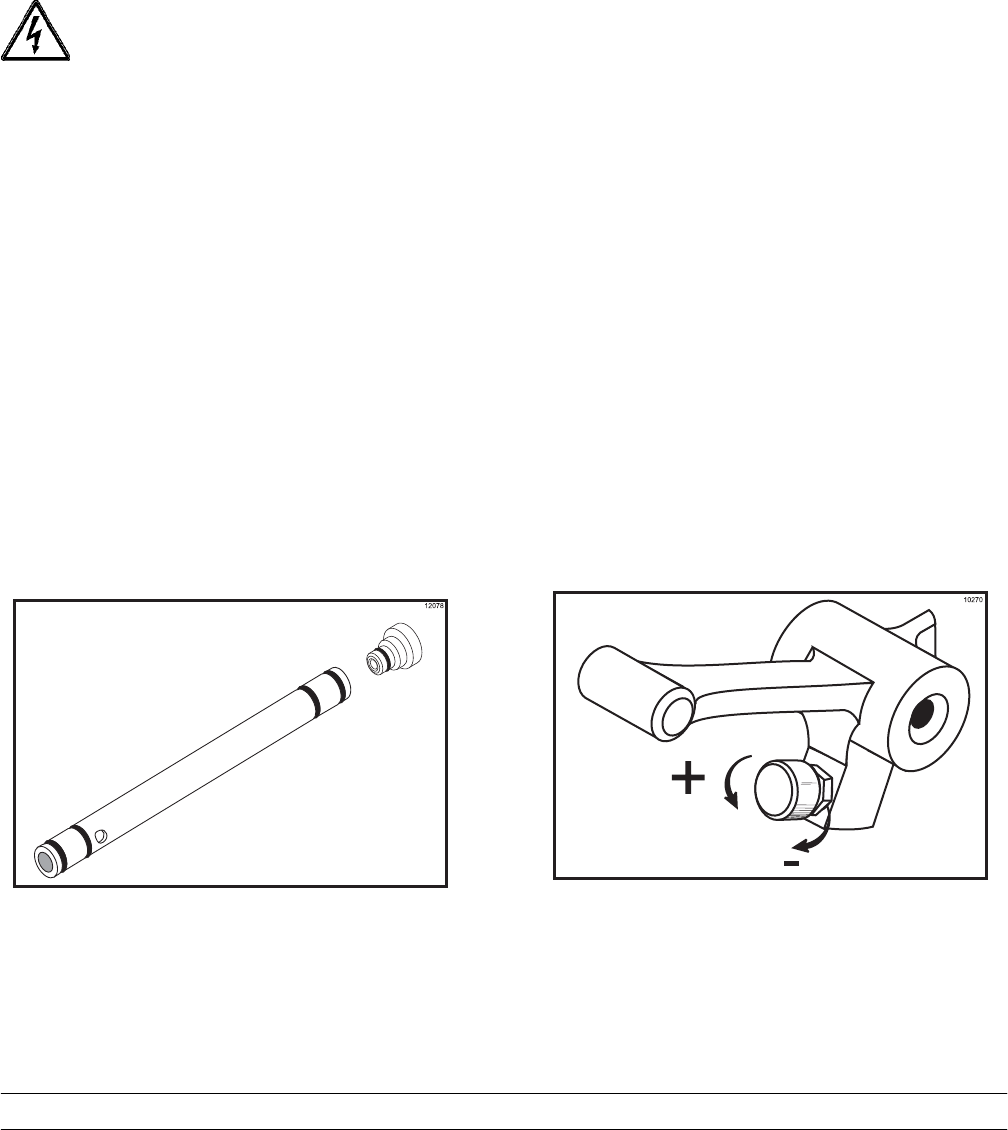
Adjustable Draw Handle
These units feature an adjustable draw handle to
provide the best portion control. The draw handle
should be adjusted to provide a flow rate of 5 to 7-1/2
oz. (148 to 222 ml) of product per 10 seconds. To
INCREASE the flow rate, turn the screw
COUNTERCLOCKWISE. T urn the screw
CLOCKWISE to DECREASE the flow rate. During
“Sanitizing” and “Rinsing”, the flow rate can be
increased by removing the pivot pin and placing the
restrictive bar on the TOP. When drawing product,
always place the restrictive bar on the bottom.
Figure 2
IMPORTANT: Once thedraw rate is set, tighten the
lock nut with a wrench.