


18
Models 750, 751, 754, 774, 794Operating Procedures
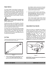
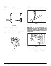
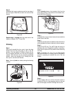
Step 5
Install the draw valve(s). Slide the t wo o -rings into the
grooves on the draw valve(s), and lubricate.
Figure 12
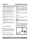
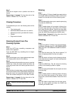
Note: Models 754, 774 and 794 have three draw
valves.
Lubricate the inside of the freezer door spout(s), top
and bottom, and insert the draw valve(s) from the
bottom until the slot in the draw valve(s) comes into
view.
Figure 13
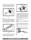
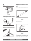
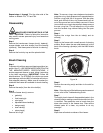
Step 6
Install the adjustable d raw handle(s). Slide the o-ring
into the groove on t he pivot pin, and lubricate.
Figure 14
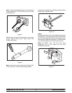
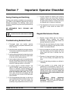
Slide the fork over the bar in the slot of the draw valve.
Secure with p ivot pin.
Note: Models 754, 774 and 794 have three draw
handles. Slide the fork of the draw handle in the slot of
the draw valve, starting from the right. Slide the pivot
pin through each draw handle as you insert them int o
the draw valves.
Figure 15
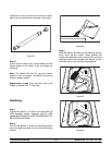
Note: These units feature adjustable draw handles to
provide the best portion control. The draw handles can
be adjusted for different flow rates. See page 14 for
more information on adjusting these handles.