


ENGLISH
4
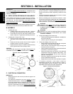
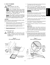
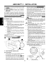
Equipotential ground
lug and symbol
(European ovens)
Cable clamp
Terminal
block
Connector
(3-phase ovens only)
Wiring
connections
(3-phase ovens
only)
SECTION 2 - INSTALLATION
IMPORTANT
IT IS THE
CUSTOMERS RESPONSIBILITY TO REPORT ANY
CONCEALED OR NON-CONCEALED DAMAGE TO THE
FREIGHT COMPANY.
A. INSTALLATION OPTIONS & KIT AVAILABILITY
If the installation will require two or three ovens to be stacked,
you must use the separately-available Stacking Kit (P/N
T2114STACK). One Kit is required for a two-stack, while two
kits are required for a three-stack.
Stacking more than three
ovens is not permitted.
Wherever the Stacking Kits instructions are different from those
listed below, follow the instructions provided with the Kit.
B. ASSEMBLY
1. Installing the Legs
a. Carefully tilt the oven onto its rear side. The front
(controller) side should be facing directly upwards.
b. Thread the four legs into the holes provided on the
bottom of the oven. Tighten them until they are secure.
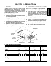
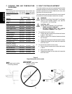
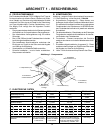
2. Installing the Conveyor End Trays
a. Press one of the conveyor end trays down over the
end plate of the conveyor frame, as shown in Figure
2.
b. Fasten the end tray in place with one of the supplied
8-32x3/8 screws, as shown in Figure 2.
c. Repeat the above steps to install the second end tray
at the opposite end of the conveyor frame.
CAUTION
THE SUPPLIED LEGS
AND THE END TRAYS MUST BE
FASTENED IN PLACE BEFORE OPERATING THE OVEN.
The toasters power cord and plug provide an electrical
ground connection. A separate equipotential ground con-
nection must also be made if required by national or local
codes.
Consult all applicable national and local codes for further
electrical connection requirements.
1. Before proceeding with the electrical connection, check
that the electrical supply matches the ovens requirements.
Refer to the serial plate and to the
Electrical Specifications
table (in Section 1 of this Manual).
WARNING
ENSURE THAT BOTH THE CIRCUIT BREAKER/
FUSED DISCONNECT
AND THE POWER ON/OFF (I/
O) SWITCH ARE IN THE O (OFF) POSITION BEFORE
PROCEEDING.
WARNING
ENSURE THAT ANY PACKING MATERIAL RESIDUE
HAS BEEN REMOVED FROM INSIDE THE OVENS
COOKING CHAMBER.
2. Single-phase Mighty Chef ovens only:
Check that the appropriate receptacle is available for
the power cord plug.
Insert the power cord plug into its receptacle.
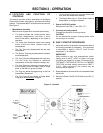
3. Three-phase Mighty Chef ovens only:
Remove the two screws that hold the rear cover panel
in place; then, remove the cover panel.
Insert the end of the electrical supply through the
connector shown in Figure 3.
Attach the electrical supply wires to their terminal block
connections, as shown in Figure 3.
Secure the supply wires to the floor of the electrical
compartment using the supplied cable clamp. The
wires must not interfere with the drive chain and
sprocket. See Figure 3.
Secure the supply as it passes through the connector
on the outside wall of the oven.
Replace the rear wall of the oven and fasten it in place.
4. If required by national or local codes, connect an
equipotential ground wire to the lug shown in Figure 3.
The equipotential ground connection must meet all
applicable national and local code requirements.
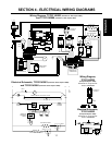
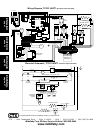
C. ELECTRICAL CONNECTION
IMPORTANT
Wiring diagrams for the oven are provided on pages 9-10
of this Manual.
The electrical connection to the oven requires a circuit
breaker/fused disconnect. Consult applicable national and
local code requirements to determine the rating of the
breaker/disconnect. Electrical specifications are listed on
the ovens serial plate and in the
Electrical Specifications
table (in Section 1 of this Manual).
Figure 2 - End Tray Installation
Position tray
1
Fasten in
place
with screw
2
Repeat for
second tray
3
Figure 3 - Electrical Connections