


6
3
2, 5
F
G
3
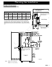
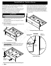
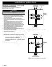
Cabinet/countertop depth is at discretion of customer but
cabinet face MUST NOT protrude further than rear of front
panel, see product dimensions.
4
Consult local code for exact location requirements.
5
Not applicable for cabinets more than a horizontal
distance of 10” (254mm) from the edge of the range.
1
Vertical to combustibles directly above cooking surface;
if installing an overhead vent hood, also check the hood
specifications for minimum required clearances.
2
Measured from range top panel.
Non-combustible
surface along
back wall
recommended
30” (762mm)
Min.
1
36 1/2”
(927mm)
Max.
13” (330mm)
Max.
5
Suggested
location of
utilities
4
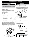
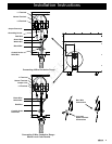
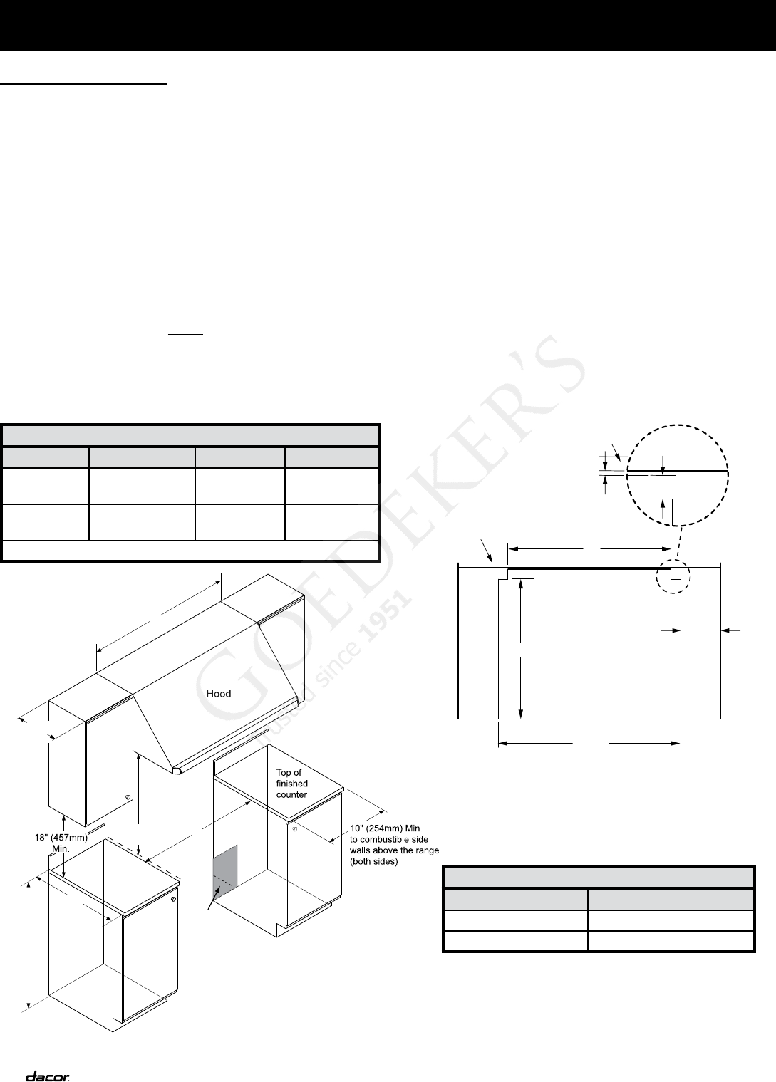
Planning the Installation
Cabinet Layout
Carefully check the location where the range is to be
installed. For best performance, the range should be placed
away from drafts that may be caused by doors, windows and
heating and air conditioning outlets.
To reduce the risk of personal injury and to reduce
accumulated smoke in the room, Dacor strongly recommends
installing a range hood. A range hood should project
horizontally a minimum of 5 inches beyond the face of the
cabinets.
All maximum and minimum dimensions and clearances
shown in the diagrams below must be maintained for safe
operation.
The range may be installed flush to the rear wall.
Dacor strongly recommends installing a non-combustible
material on the rear wall above the range and up to the vent
hood or installation of a backguard. It is not necessary to
install non-combustible materials behind the range below the
countertop height.
Any openings in the wall behind the appliance or in the floor
underneath it must be sealed.
•
•
•
•
•
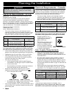
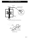
CUT-OUT DIMENSIONS
Range Model F G H
ER36D
42” (1067mm)*
36” (914mm)**
36 1/16”
(916mm)**
33 ½”
(848mm)
ER48D
54” (1372mm)*
48” (1219mm)**
48 1/16”
(1221mm)**
43 ½”
(1102mm)
* Recommended **Minimum
All tolerances: +1/16”, -0 (+1.6mm, -0)
Unless otherwise stated
Gas and Electrical Service
The shaded area shown denotes the location of the gas
inlet and the electrical junction box/receptacle. This is the
recommended location. For replacement purposes, the
location of the existing utilities may be utilized provided they
do not interfere with the sides or rear of the range. Check
local building codes for permissible gas valve locations.
An external manual shut-off valve must be installed between
the gas inlet and the range, for the purpose of turning on or
shutting off gas to the appliance.
The installation must allow for the following:
Access to the gas shut-off valve when the unit is installed.
Access to the remote circuit breaker panel/fuse box, when the
range is in place.
The gas supply piping and shut-off valve, and the electrical
junction box/receptacle must be located so they do not
interfere with the range when it is installed.
The junction box and gas shut off valve must be located
so that the range can be pulled out for service while the
appliance remains connected.
•
•
•
•
•
•
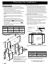
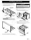
G
10" (254 mm) Min.
to combustible side
walls above the range
(both sides)
non-combustible
Minumum Countertop Height:
30 1/4” (768 mm)
Maximum Countertop Height:
36 1/2” (927 mm)
rear wall recommended
Backsplash
3/8" (10 mm)
Min. flat countertop
overhang
H
2 13/16"
(71.4 mm)
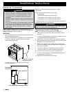
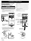
3
Cutout with Optional ERV Raised Vent (Top View)
Standard Cutout with
Range Hood
APPROVED RAISED VENT MODEL NUMBERS
Range Model ERV Raised Vent Model
ER36D ERV36-ER
ER48D ERV48-ER
IMPORTANT: See the raised vent installation instructions
for the duct and electrical installation requirements. Use
only the raised vent models specified below.