


7
Preparing for Installation
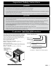
WARNING
If the gas or electric service provided does not meet the
product specifications, do not proceed with the installation.
Call the dealer, the gas supplier or a licensed electrician.
Before installing the range, you must locate and secure the
anti-tip bracket to the floor.
•
•
IMPORTANT: Within the Commonwealth of Massachusetts, this
appliance must be installed by a licensed plumber or gas fitter.
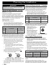
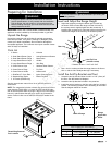
Unpack the Range
Unpack the parts box and verify that all required components
have been provided. If any item is missing or damaged, please
contact your dealer immediately. Do not install a damaged or
incomplete appliance. The customer must report cosmetic issues
within 30 days of installation.
Parts List
3 Grates
2 Small Stack Burner Caps
2 Small Stack Burner Rings
2 Large Stack Burner Caps
2 Large Stack Burner Rings
2 Crown Burner Caps
2 Crown Burner Rings
2 Crown Burner Heads
1 GlideRack
™ Oven Rack
2 Standard Size Racks
3 18” Racks (ER48D only)
•
•
•
•
•
•
•
•
•
•
•
6 Knobs
Anti-tip Bracket w/Screws
Meat Probe
Griddle
Wok Ring
Stainless Steel Cleaner
Pry Stick
Literature Kit
Ignitor Cleaning Brush
Broiler Pan/Grill
•
•
•
•
•
•
•
•
•
•
See the use and care manual for a list of optional parts and
accessories.
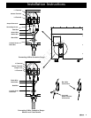
NOTE: The range also includes a thread ring removal tool for the
crown burners (PN101539). It is taped in place behind the right
side of the kick panel when the range is shipped from the factory.
Leave it in place unless the spill trays need to be removed for
service. Return it after use so that it is available if needed in the
future.
Installation Instructions
WARNING
Do not connect the unit to gas or power before proceeding with
the following sections.
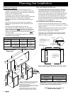
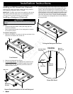
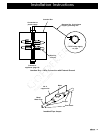
Level and Adjust the Range Height
Adjust the height by turning the bottom part of each leg
as shown. Raise or lower the range until the trim around
the cooktop area is slightly higher than the counter-top. If
installing with a raised vent, adjust the height so that the trim
matches the height of the vent’s top in the down position.
Use a level to make sure that the range does not tilt front to
back or side to side. Readjust the legs if necessary.
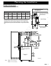
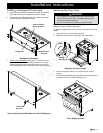
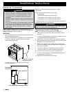
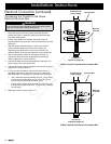
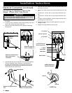
Install the Anti-Tip Bracket and Foot
Locate the anti-tip foot and lower it until it is 1/16" (2mm) off
the floor. See the bottom left diagram.
Locate the anti-tip bracket included in the parts box.
Install the anti-tip bracket on the floor using the four included
screws. The mounting location varies according to the model.
See the diagram below for location.
ANTI-TIP BRACKET PLACEMENT
Dimension ER36D ER48D
J 7 1/2” (191mm) 19” (483mm)
K 6 1/2” (165mm) 6 1/4” (159mm)
1.
2.
1.
2.
3.
J
K
Top View
Back of Range
Range
Right Side
Panel
Back of Range
Anti-Tip Foot
(location varies)
1 1/4” *
down
up
Rear Leg
Thread Ring Removal
Tool Location
* Distance to floor: 4 1/16” to 5 5/16”