Vantage 6000™ Series and Glass Door Merchandisers Reach-Ins Service and Installation Manual
For customer service, call (800) 733-8829, (800) 773-8821, Fax (989) 773-3210, www.deleld.com
4
Vantage 6000™ Series and Glass Door Merchandisers Reach-Ins Service and Installation Manual
5
For customer service, call (800) 733-8829, (800) 773-8821, Fax (989) 773-3210, www.deleld.com
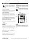
Do not place hot pans on the white ABS liner. Do
not throw items into the storage area. Failure
to heed these recommendations could result in
damage to the interior of the cabinet or the blower
coil.
After plugging the unit in, the unit will operate immediately.
Temperature Control Instruction
Refrigerators: A thermostat, located at the top of the refrigera-
tor evaporator housing, controls the temperature in the box. The
factory setting for the control is “4” and maintains about 38°F
(3°C) in the box. Set toward “1” for higher temperature and
toward “7” for lower temperatures.
Freezers: A thermostat, located at the top of the freezer on
the right hand side of the evaporator housing, controls the
temperature in the box. The factory setting for the control is “4”
and maintains about -3°F (-19°C) in the box. Set toward “1” for
higher temperature and toward “7” for lower temperatures.
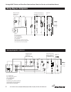
Refrigeration cycle
During the refrigeration cycle, for a freezer, the timer supplies
power to the temperature control, evaporator fan motors and
activates the condensing unit as needed. The fan operates only
during the refrigeration cycle. Any door being opened turns off
the fan motors and turns on the interior light.
1) The temperature control allows for the coil clearing after
each off cycle and before the compressor runs again.
2) Evaporator fan motors run continually on refrigerators only.
3) Interior lights are activated by the jamswitch when any door
is opened.
4) The anti-sweat heater around each door opening cycles
with the compressor.
Defrost Cycle
When defrost control goes into defrost, power to the condensing
unit and evaporator fans is interrupted and the defrost heater
is energized. The defrost heater warms the evaporator coil
thereby melting all frost accumulated during the previous refrig-
eration cycle. Once all frost is eliminated, the temperature of
the coil continues to rise until it reaches 70°F (13°C). When this
temperature is sensed by the defrost limit control, the defrost
control switches to refrigeration mode.
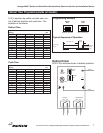
If for any reason the timer remains in defrost for a period of time
greater than 40 minutes, a back-up defrost termination is also
provided. It can be changed by adjusting the electric control
switches as shown on page 7.
Freezer Defrost Control
All freezers are equipped with an Air-o-tronics defrost timer for
automatic defrosting of the evaporator coil. See page 7. The
defrost timer cannot be adjusted to the time of day.
Operation
The electric defrost controller is preset at the factory to provide
a defrost cycle every 6 hours (4 defrosts per day). If it is neces-
sary to change the number of defrosts due to unusual operating
conditions, it can be accomplished by adjusting switches as
shown on page 7.
Even under the most severe operating conditions
it should not be necessary to set the back-time
greater than 60 minutes. Consult the factory if
complete de-icing of the coil is not accomplished.
CAUTION
CAUTION
Operation Information
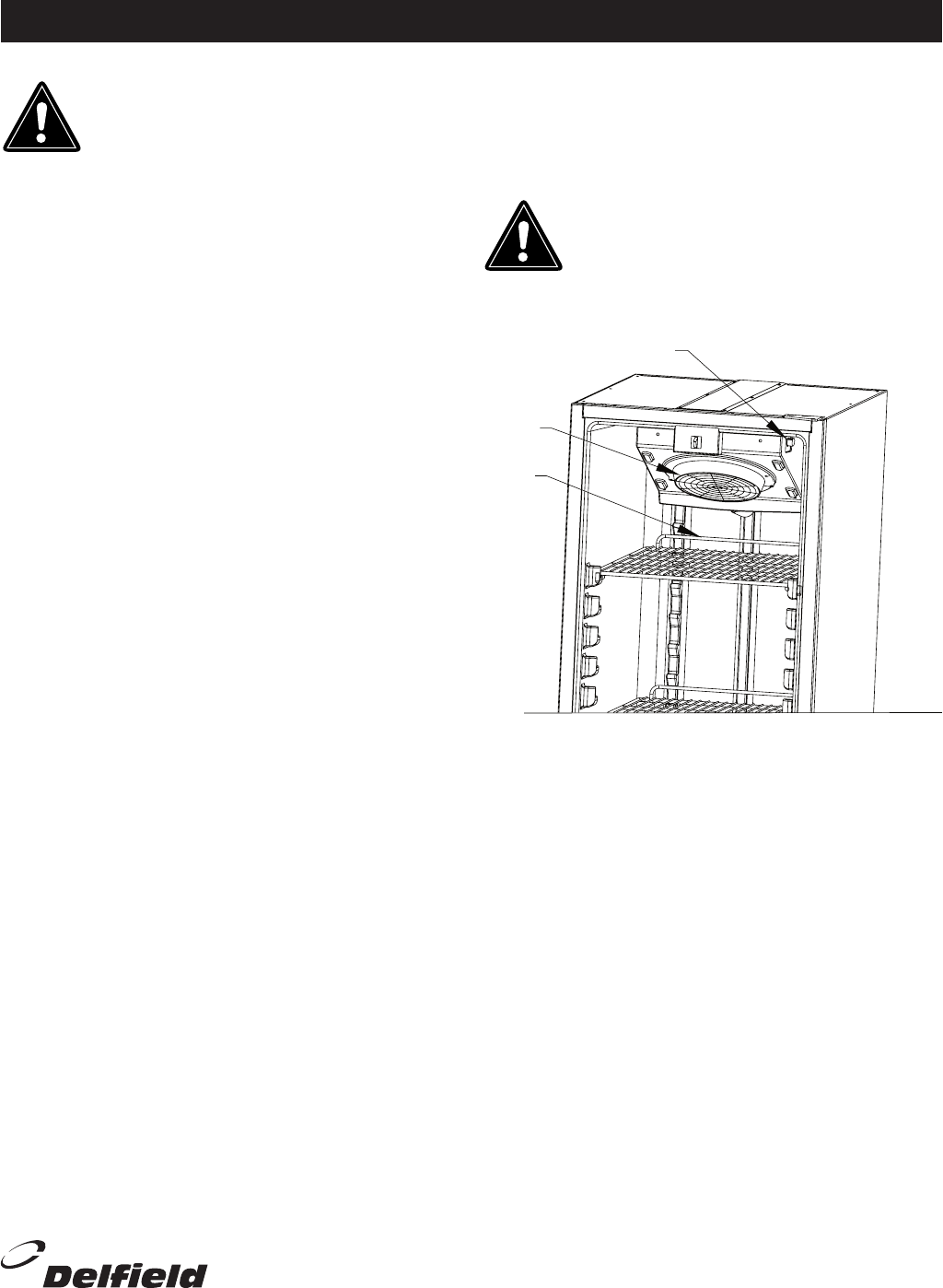
Evaporator
Fan
Product
Stop Bar
Unit loading
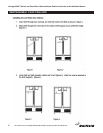
When loading the top shelf, maintain 4” of space between the fan
guard and product. Do not allow product to pass stop bar on the back
of the shelf. No product should be placed between the back shelf
supports and center ribs in order to maintain good airow. Failure to
keep this space can cause inconsistent food temperature from top to
bottom.
Thermostat


