


22
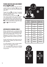
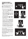
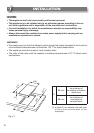
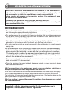
CONNECTING OF THE POWER SUPPLY CABLE
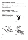
• Unhook the terminal board cover by inserting a screwdriver into the two hooks A (fig.
5.1).
• Open the cable gland by unscrewing screw F (fig. 5.3), unscrew the terminal screws
and remove the cable.
• The new supply cable, of suitable type and section, is connected to the terminal board
following the diagram of fig. 5.2.
FEEDER CABLE SECTION “Type H05RR-F”
2 0-240 V ~ 3 x 1.5 mm
2
2 0-240 V
E
N
L
E Earth
N Neutral
L Live
Fig. 5.2
Fig. 5.3
F
WARNING: If the power supply cable
is damaged, it must be replaced only
by an authorised service agent in
order to avoid a hazard.
A
Fig. 5.1
3
3
3600 W MAX (15.6 A)