


Page 2.
MODEL SIG110LED
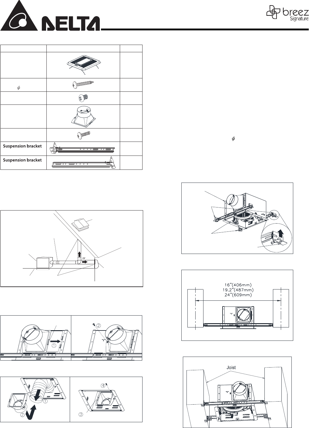
SUPPLIED ACCESSORIES
Part name Appearance Quantity
Grille
1
Tapping Screw
(ψ
4x25)
4
Screw
#8-32x1/4”
4
Duct connector 1
Duct Screw
(M4x12)
1
13”(318.5)
2
13”(318.5)
2
Inches (mm)
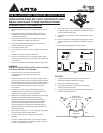
INSTALLATIONS
Proper insulation around the fan to minimize building heat loss
and gain.
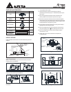
Attach Duct Connector
Option 1. Attach the duct connector from outside, and secure
using the duct screw (M4X12).
Insert tab into
slot in housing
Duct screw(M4X12)
from Parts Bag
Option 2. Attach the duct connector from the housing can inside,
and secure using the duct screw (M4X12).
Pull existing ductwork
into Housing
Insert tab into slot
in Housing
Duct screw(M4X12)
from Parts Bag
Note: Remove the tape from the damper and adaptor before
installation.
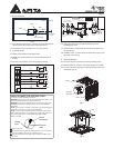
1. Using suspension brackets
1-1. Sliding suspension brackets are provided to allow for
positioning of the housing anyw here between joists up to a
span of 24”.
1-2. Insert the suspension brackets into the channels on the
housing. Make sure the tabs face up as shown. (Fig. C)
1-3. Extend the suspension brackets to t the width of the joists.
Hold the fan in place by wrapping the suspension bracket tabs
around the bottom of the joist. Make sure the fan body is level
and perpendicular to the joist. (Fig. D & E)
1-4. Ensure that the distance between the ceiling and fan body is
appropriate for mounting the grille.
1-5. Secure the suspension brackets to the joists with nails or by
using the tapping screws ( 4x25) through holes near nails.
1-6. Secure the suspension bracket to the fan body using the
screws (#8-32 x 1/4").
1-7. Follow steps 2 to 6 of the installation to complete the
installation work.
Suspension
Bracket II
Suspension
Bracket I
Body
Tab
Fig. C
Fig. D
Fig. E
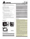
ψ
Roof cap
(with built-in
damper)
Short piece of exible
duct helps alignment
and absorbs
sound
Wall cap
(with built-in
damper)
Caulk termination
to duct
Fan housing
Seal gap
around housing