


14
CAST IRON STOVE AND BURNER SYSTEM
105501
CDVBN(A) AND CDVBP(A)
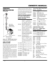
Flat Ceiling Installation
1. Cut a 10" square hole in the ceiling us-
ing the locating hole as a center point.
The opening should be framed to
10"x10" (254mm x 254mm) inside di-
mensions, as shown in Figure 22 on
page 12 using framing lumber the same
size as the ceiling joists. If the area
above the ceiling is an insulated ceil-
ing or a room, nail firestop from the
top side. This prevents loose insulation
from falling into the required clearance
space. Otherwise, install firestop below
the framed hole. The firestop should be
installed with no less than three nails
per side (see Figure 31, page 15).
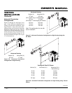
2. Assemble the desired lengths of pipe
and elbows necessary to reach from the
burner system flue up through the
firestop. All connections must be
sealed with high temperature silicone
sealant as specified in the second warn-
ing statement on page 10. Be sure all
pipe and elbow connections are fully
twist-locked (see Figure 21, page 12).
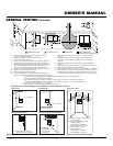
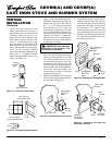
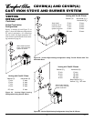
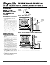
1. Determine the route your vertical vent-
ing will take. If ceiling joists, roof
rafters, or other framing will obstruct
the venting system, consider an offset
(see Figure 30) to avoid cutting
loadbearing members.
Note:
Pay spe-
cial attention to these installation in-
structions for required clearances (air
space) to combustibles when passing
through ceilings, walls, roofs, enclo-
sures, attic rafters, etc. Do not pack
air spaces with insulation. Also note
maximum vertical rise of the venting
system and any maximum horizontal
offset limitations. Offsets must fall
within the parameters shown in Fig-
ure 18 on page 9.
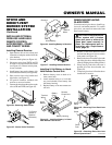
2. Set the stove in desired location. Drop
a plumb line down from the ceiling to
the position of the burner system exit
flue. Mark the center point where the
vent will penetrate the ceiling. Drill a
small locating hole at this point.
Drop a plumb line from the inside of
the roof to the locating hole in the ceil-
ing. Mark the center point where the
vent will penetrate the roof. Drill a
small locating hole at this point.
Figure 30 - Offset with Wall Strap and 45
°
Elbows
45° Elbow
Wall Strap
Roof
Flashing
Ceiling Firestop
INSTALLATION FOR
VERTICAL TERMINATION
NOTICE: Use rigid pipe only. Flex
venting is not to be used with a
vertical termination.
VENTING
INSTALLATION
Continued
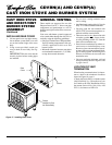
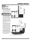
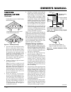
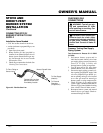
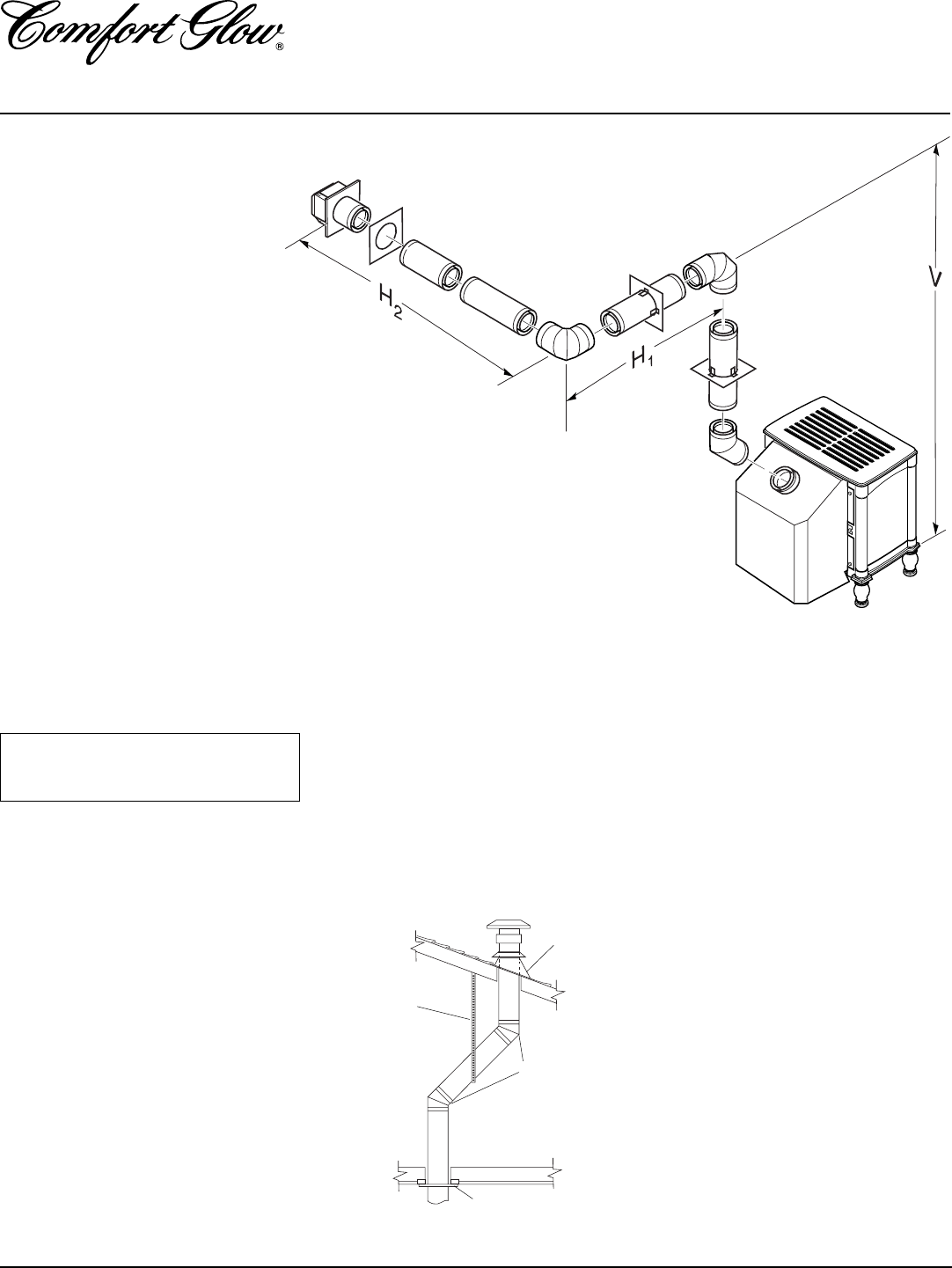
Venting with Two 90° Elbows
Vertical (V) Horizontal (H
1
) +
Horizontal (H
2
)
5' min. 6' max.
6' min. 12' max.
7' min. 18' max.
8' min. 20' max.
20' max. 20' max.
Figure 29 - Horizontal Termination Configuration for Rigid Venting Using Two 90
°
Elbows with Termination at 90
°
with Stove