


15
105501
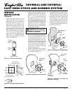
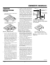
OWNER’S MANUAL
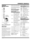
VENTING
INSTALLATION
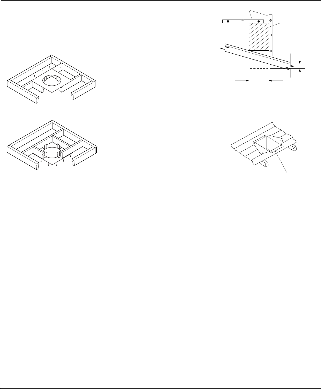
Continued
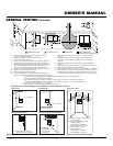
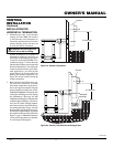
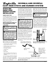
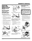
Figure 31 - Installing Firestop
If area above is not a room, install
firestop below framed hole.
If area above is a room, install firestop
above framed hole.
Continued
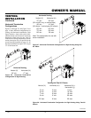
3. Cut a hole in the roof using the locating
hole as a center point. (Cover any ex-
posed open vent pipes before cutting
hole in roof.) The 10"x10" hole must
be measured on the horizontal; actual
length may be larger depending on the
pitch of the roof. There must be a 1"
clearance from the vent pipe to combus-
tible materials. Frame the opening as
shown in Figure 22 on page 12.
4. Connect a section of pipe and extend
up through the hole.
Note:
If an offset is needed to avoid
obstructions, you must support the vent
pipe every 3 feet. Use wall straps for
this purpose (see Figure 30, page 14).
Whenever possible, use 45° elbows in-
stead of 90° elbows. The 45° elbow of-
fers less restriction to the flow of the
flue gases and intake air.
5. Place the flashing over the pipe
section(s) extending through the roof.
Secure the base of the flashing to the
roof and framing with roofing nails.
Be sure roofing material overlaps the
top edge of the flashing as shown in
Figure 30, page 14. There must be a
1" clearance from the vent pipe to
combustible materials.
6. Continue to add pipe sections until the
height of the vent cap meets the mini-
mum building code requirements de-
scribed in Figure 18 on page 9.
Note:
You must increase vent height for steep
roof pitches. Nearby trees, adjoining
rooflines, steep pitched roofs, and other
similar factors may cause poor draft or
down-drafting in high winds. Increasing
the vent height may solve this problem.
7. Twist-lock the vent cap onto the last
section of vent pipe and seal outer pipe
connection with high temperature sili-
cone sealant as specified in the second
warning statement on page 10.
Note:
If the vent pipe passes through any
occupied areas above the first floor, including
storage spaces and closets, you must enclose
pipe. You may frame and sheetrock the enclo-
sure with standard construction material. Make
sure and meet the minimum allowable clear-
ances to combustibles. Do not fill any of the
required air spaces with insulation.
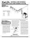
Cathedral Ceiling Installation
1. Remove shingles or other roof cover-
ing as necessary to cut the rectangular
hole for the support box. Mark the out-
line of the cathedral ceiling support box
on the roof sheathing using the locat-
ing hole as a center point.
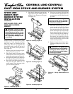
2. Cut the hole 1/8" larger than the sup-
port box outline (see Figure 32).
3. Lower the support box through the hole
in the roof until the bottom of the box
extends at least 2" below the ceiling
(see Figure 32). Align the support box
vertically and horizontally using a level.
Temporarily tack the support box in
place through the inside walls and into
the roof sheathing.
4. Using tin snips, cut the support box from
the top corners down to the roofline and
fold the resulting flaps over the roof
sheathing (see Figure 33). Apply a bead
of non-hardening mastic around the top
edges of the support box to make a seal
between the box and the roof. Nail in
place with roofing nails. Remove any
combustible material that might be in-
side of the support box.
5. Complete the cathedral ceiling installa-
tion by following the same procedures
outlined in steps 2 through 7 for Flat
Ceiling Installation, pages 14 and 15
.
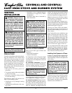
Figure 32 - Cathedral Ceiling Support
Box Installation
Non-hardening Mastic under all
edges of support box before nailing
Figure 33 - Installed Cathedral Ceiling
Support Box
Cut hole 1/8" larger than support
box when projected onto roofline
2" minimum below
finished ceiling
Cathedral ceiling
support box
Level