


21
105501
OWNER’S MANUAL
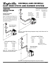
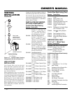
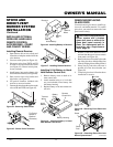
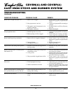
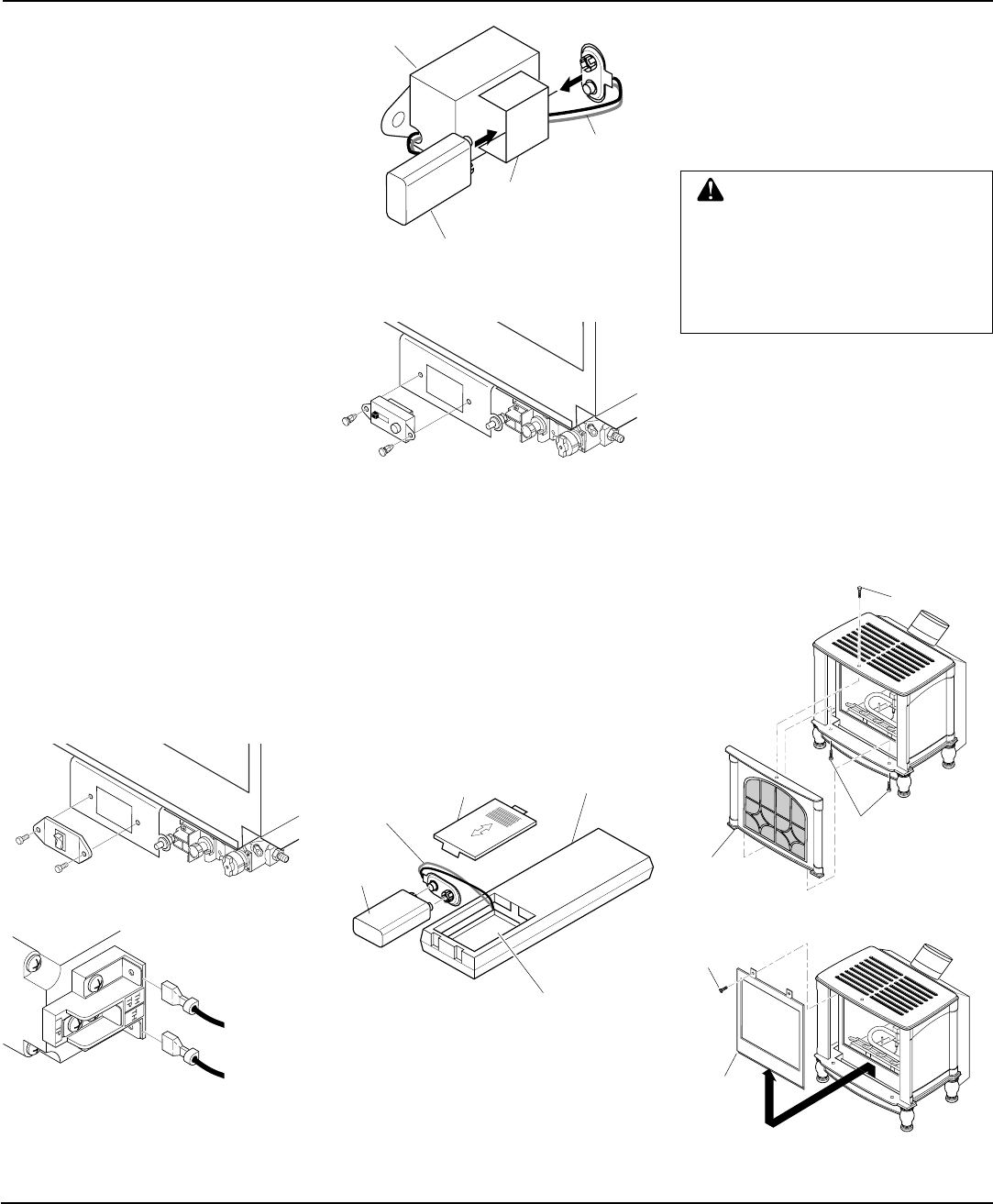
REMOVING/REPLACING
GLASS DOOR
CAUTION: Do not operate this
burner system with a broken
glass door panel or without the
glass door panel securely in
place. For replacement part in-
formation see
Replacement
Parts
, page 30.
1. Remove 2 bolts from bottom of stove
and one from the top of stove to remove
front panel (see Figure 49).
2. Remove the screws from the 2 tabs at the
top of the glass door while holding door
securely keeping it from falling forward.
3. Grasp door by both sides and ease it
upward off of the lower bracket (see
Figure 50).
4. To replace glass door, follow the above
instructions in reverse.
You must remove glass door to install logs,
lava rock, and ember material. To remove
glass door, you must first remove the front
panel on stove body.
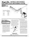
STOVE AND
DIRECT-VENT
BURNER SYSTEM
INSTALLATION
Continued
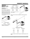
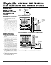
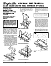
Figure 46 - Installing Battery in Receiver
Figure 48 - Installing Battery in Hand-
Held Remote Control Unit
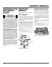
Installing 9-Volt Battery in Hand-
Held Remote Control Unit
1. Remove battery cover on back of re-
mote control unit
2. Attach terminal wires to a 9-volt bat-
tery (not included). Place battery into
the battery housing.
3. Replace battery cover onto remote con-
trol unit.
Terminal
Wires
Battery
Cover
9-Volt
Battery
Remote
Control Unit
Battery Housing
9-Volt Battery
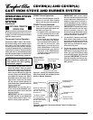
Receiver
Battery
Clip
Terminal
Wires
Bolt
Bolt
Stove Front
Panel
L
O
H
I
P
I
L
O
T
OFF
ON
Figure 47 - Installing Remote Receiver
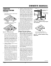
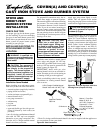
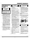
Figure 44 - Removing Switch Plate
L
O
H
I
P
I
L
O
T
OFF
ON
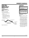
Figure 45 - Control Valve Terminals
To Control
Switch or
Optional
Accessory
Figure 50 - Removing Glass Door from
Burner System Insert
Figure 49 - Removing Front Panel from
Stove
Screw
Glass
Door
Continued
INSTALLING OPTIONAL
WIRELESS HAND-HELD
REMOTE CONTROL
ACCESSORIES - CGHRC
AND CGHRCT SERIES
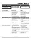
Installing Remote Receiver
1. Open bottom door on stove body and
locate the switch plate on the left of the
valve bracket.
2. Unscrew switch plate (see Figure 44).
3. Disconnect wires from THTP and TH
on control valve that lead to the switch
(see Figure 45). Discard switch plate,
screws, and nuts.
4. Install battery into receiver battery clip
and connect to terminals (see Figure 46).
5. Place receiver into valve bracket and
align holes (see Figure 47).
6. Use push-in fasteners included with
receiver to secure to bracket.
7. Connect the wires from the receiver to the
valve at TH and THTP (see Figure 45).