


7
105501
OWNER’S MANUAL
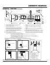
WARNING: Never touch the
blower wheel while in operation.
7. Peel off the backing paper and stick the
supplied wiring diagram decal on the
inside of rear cover on right side oppo-
site control.
WARNING: Failure to position
the parts in accordance with sup-
plied diagrams or failure to use
only parts specifically approved
with this stove and burner sys-
tem may result in damage or per-
sonal injury.
8. Connect or reconnect gas supply to
stove and burner system per Connect-
ing Stove/Burner System to Gas Sup-
ply on page 19 of this manual.
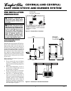
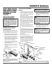
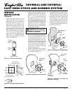
INSTALLING OPTIONAL
BLOWER ACCESSORY
1. Align the holes in the top mounting tabs
of blower with holes in wall of rear
cover (see Figure 16). Using the 4
screws provided, mount blower and
tighten screws securely.
Note:
For CDA3620T, make sure the ther-
mal switch has been properly installed to
fit against the back of the burner system.
2. Make sure all wire connections to ter-
minals on blower motor (and thermal
switch where applicable) are securely
attached and that the screw retaining the
green ground wire is tight.
3. Place speed control on back wall inside
of rear cover and push the plastic con-
trol shaft through opening (see Figure
16).
4. While supporting speed control, secure
control shaft with lock nut by pushing and
turning lock nut with pliers clockwise
until tight against the side of rear cover.
Place control knob provided onto shaft
(see Figure 16).
5. Plug in blower power cord.
6. Check to make sure that the power cord
is completely clear of the blower wheel
and that there are no other foreign ob-
jects in blower wheel. Turn blower on
and check for operation. Turn blower
off by rotating knob fully counterclock-
wise before continuing.
NOTICE: If installing blower in an
existing stove with burner sys-
tem with gas connections, shut
off gas supply and disconnect
burner system from gas supply.
Contact a qualified service per-
son to do this.
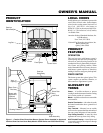
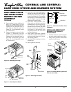
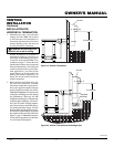
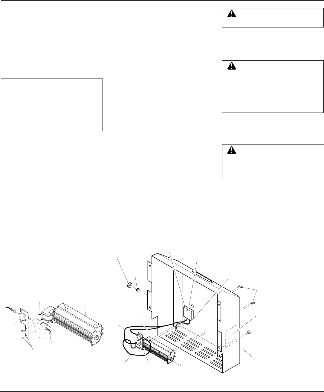
Attaching Thermal Switch to
CDA3620T Thermostatically-
Controlled Blower
When installing the CDA3620T thermostati-
cally-controlled blower accessory, you must
first secure the thermal switch to the blower.
1. Remove the two hex head screws on the
blower assembly as shown in Figure 15.
2. Place the green wire between the bot-
tom hole on the thermal switch bracket
and the bottom hole on the blower as-
sembly. Insert one of the hex screws
into all three pieces and tighten.
3. Insert the top screw through the ther-
mal switch bracket and into the blower
assembly. Tighten screw.
4. Connect the blue wire on the blower
assembly to the right side of the ther-
mal switch.
5. Connect the black wire to the left side
of the thermal switch.
Installing GA3750/CDA3620T
Blowers
WARNING: A qualified ser-
vice person must connect burner
system to gas supply. Follow all
local codes.
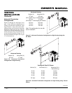
Figure 15 - Attaching Thermal Switch to
CDA3620T Thermostatically-Controlled
Blower Accessory
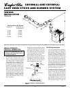
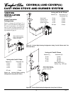
Figure 16 - Installing Optional Blower Accessory (Thermostat Model CDA3610T
Shown)
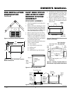
CAST IRON STOVE
AND DIRECT-VENT
BURNER SYSTEM
ASSEMBLY
Continued
Blower
Mounting Screws
(Included in
Hardware Pack)
Blower
Control Knob
Control Shaft
Rear Cover
Speed Control
Power Cord
Lock
Nut
White
Wire
Blue
Wire
Green
Ground Wire
Black
Wire
Wiring
Diagram
Decal
Continued
Thermal
Switch
with
Bracket
Black
Wire
White Wire
Green
Wire
Blue Wire
Hex Head
Screws
Blower
Assembly