


www.desatech.com
118197-01C 13
Note:Verticalrestrictormustbeinstalledinall
verticalinstallations.
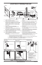
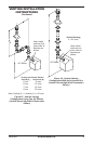
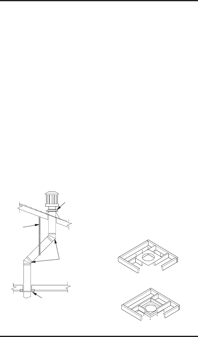
1. Determinetherouteyourverticalventing
willtake.Ifceilingjoists,roofraftersorother
framingwillobstructtheventingsystem,
consideranoffset(seeFigure19)toavoidcut-
tingloadbearingmembers.Note:Payspecial
attentiontotheseinstallationinstructionsfor
requiredclearances(airspace)tocombustibles
whenpassingthroughceilings,walls,roofs,
enclosures,atticrafters,etc.Donotpackair
spaceswithinsulation.Alsonotemaximum
verticalriseoftheventingsystemandany
maximumhorizontaloffsetlimitations.
2. Setthereplaceindesiredlocation.Dropa
plumblinedownfromtheceilingtotheposi-
tionofthereplaceexitue.Markthecenter
pointwheretheventwillpenetratetheceiling.
Drillasmalllocatingholeatthispoint.
Dropaplumblinefromtheinsideoftheroof
tothelocatingholeintheceiling.Markthe
centerpointwheretheventwillpenetratethe
roof.Drillasmalllocatingholeatthispoint.
1. Cuta10
3
/
4
"squareholeintheceilingusing
thelocatingholeasacenterpoint.Theopening
shouldbeframedto10
3
/
4
"x10
3
/
4
"(27.3cmx
27.3cm)insidedimensions,asshowninFigure
9onpage8usingframinglumberthesame
sizeastheceilingjoists.Iftheareaabovethe
ceilingisaninsulatedceilingoranatticspace,
nailrestopfromthetopside.Thisprevents
looseinsulationfromfallingintotherequired
clearancespace.Iftheareaabovetheceilingis
alivingspace,installrestopbelowtheframed
hole.Therestopshouldbeinstalledwithno
lessthanthreenailsperside(seeFigure20).
2. Assemblethedesiredlengthsofpipeand
elbowsnecessarytoreachfromthereplace
ueupthroughtherestop.Besureallpipe
andelbowconnectionsarefullytwist-locked
(seeFigure8,page8).
3. Cutaholeintheroofusingthelocatinghole
asacenterpoint.(Coveranyexposedopen
ventpipesbeforecuttingholeinroof.)The
10
3
/
4
"x10
3
/
4
"holemustbemeasuredon
thehorizontal;actuallengthmaybelarger
dependingonthepitchoftheroof.There
mustbea1"clearancefromtheventpipeto
combustiblematerials.Frametheopeningas
showninFigure9,page8.
4. Connectasectionofpipeandextendup
throughthehole.
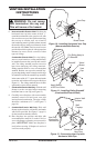
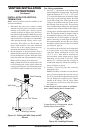
Note:Ifanoffsetisneededtoavoidobstruc-
tions,youmustsupporttheventpipeevery3
feet.Usewallstrapsforthispurpose(seeFig-
ure19).Wheneverpossible,use45°elbows
insteadof90°elbows.The45°elbowoffers
lessrestrictiontotheowoftheuegases
andintakeair.
VENTINg INSTALLATION
INSTRUCTIONS
Continued
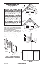
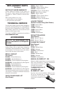
Figure 19 - Offset with Wall Strap and 45°
Elbows
45° Elbow
Wall Strap
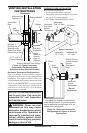
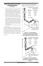
Roof Flashing
Ceiling Firestop
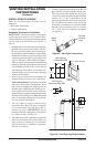
Figure 20 - Installing Firestop
If area above is a living space, install
restop below framed hole.
If area above is an attic space or insulated
area, install restop above framed hole.