


6
11.11.
11.11.
11.
12 12
12 12
12
VV
VV
V
OLOL
OLOL
OL
T DC CONNECTIONT DC CONNECTION
T DC CONNECTIONT DC CONNECTION
T DC CONNECTION
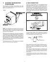
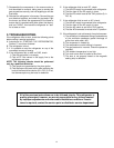
The 125 watt heating element operates the cooling unit
when the refrigerator is connected to the battery of the
vehicle. It has a current rating of about 10.5 amps; there-
fore, the wiring from the battery to the refrigerator must be
of heavy enough gauge to carry this load satisfactorily
without undue voltage drop. To ensure this, the minimum
size of wire to be used is 14 A.W.G. The terminal block for
connecting the 12V supply cable to the battery is posi-
tioned at the lower left-hand corner of the rear side (G, FIG.
8). From this terminal, the connection to the battery should
be made using ring-type clamps with tightening bolts to
ensure good contact with the battery terminals. Polarity is
not important, therefore it does not matter which wire leads
to which battery terminal.
DO NOT connect lights or any other electrical compo-
nents to the same circuit that is used by the refrigera-
tor.
9.9.
9.9.
9.
TESTING LP GAS SAFETY SHUTTESTING LP GAS SAFETY SHUT
TESTING LP GAS SAFETY SHUTTESTING LP GAS SAFETY SHUT
TESTING LP GAS SAFETY SHUT
OFFOFF
OFFOFF
OFF
The gas safety shutoff must be tested after the refrigerator
is connected to LP gas supply.
To test the gas safety shutoff, proceed as follows:To test the gas safety shutoff, proceed as follows:
To test the gas safety shutoff, proceed as follows:To test the gas safety shutoff, proceed as follows:
To test the gas safety shutoff, proceed as follows:
A. Start the refrigerator according to the instructions for
LP Gas Operation. See "
Section C. Operation Instruc-
tions
."
B. Check that the gas flame is lit. Allow it to burn a few
minutes to ensure a full, stable flame.
C. Turn the gas safety valve (B, FIG. 8) to the "OFF"
position. Within 1-2 minutes the gas safety device
within the valve should automatically close. An audible
"click" from the valve may be heard.
D. Turn the gas safety valve to the "HIGH" position (B,
FIG. 8).
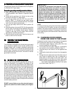
E. Without pushing in the knob (B, FIG. 8) of the gas safety
device, apply a commercial leak detection solution to
the burner jet. No bubbles should appear. Bubbles
indicate a gas leak and the safety valve must be
replaced by a qualified serviceman.
F. Rinse the burner jet with water. Light the burner and
allow it to burn for five minutes.
10.10.
10.10.
10.
120 120
120 120
120
VV
VV
V
OLOL
OLOL
OL
T AT A
T AT A
T A
C ELECTRICALC ELECTRICAL
C ELECTRICALC ELECTRICAL
C ELECTRICAL
CONNECTIONCONNECTION
CONNECTIONCONNECTION
CONNECTION
The refrigerator is equipped with a three-prong (grounded)
plug for protection against shock hazards, and should be
plugged directly into a properly grounded three-prong
receptacle. DO NOT cut or remove the grounding prong
from this plug. The power cord should be routed to avoid
direct contact with the burner cover, fuel cover or manual
gas shutoff valve knob.
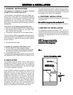
IMPORTANT:
To prevent the refrigerator from being left on and
draining the battery when the vehicle's engine is
not running and charging the battery, it is recom-
mended that an automatic cutout relay be installed
between the battery and the refrigerator toggle
switch so that the refrigerator will not draw current
when the vehicle ignition is switched off. Alterna-
tively, a suitable plug and receptacle should be
installed in the 12V supply line so that the refrig-
erator can be disconnected from the supply, as
necessary.
FUSE
A 12 amp (continuous rating) fuse should be incorporated
in the wiring of the DC supply, as near to the battery as
possible. The fuse must be in the side of the wiring which
is not connected to the chassis. For example, if the vehicle
has a negative ground, the fuse must be in the positive side
of the wiring.
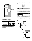
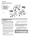
12. CHANGING DOOR HINGES
FROM ONE SIDE TO THE OTHER
If required, the door hinges can be moved to the opposite
side. Reverse the door hang in the following way:
A. Unscrew the upper hinge pin, taking care not to lose
the set of washers and bushings.
B. Lift the door from the lower hinge pin. If decorative
door panel is to be installed, proceed to Step 13.
C. Unscrew the pin and mount it on the opposite side
hinge.
D. Unscrew the travel catch and mount it on the opposite
side.
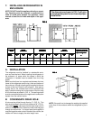
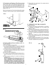
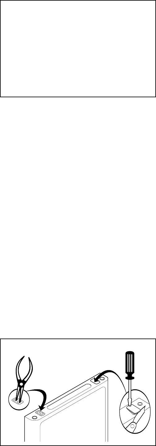
E. Change the cover plate and travel lock plate in top of
door frame to opposite side. Use a screwdriver to
press down on one edge of the cover plate. The
opposite edge will rise above the frame. Use a knife
blade under the raised edge to pop it out. See FIG. 7.
Use needle-nosed pliers to carefully lift lock plate
out of door frame. See FIG. 7.
FIG. 7