8
2. CONTROLS
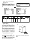
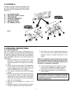
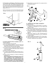
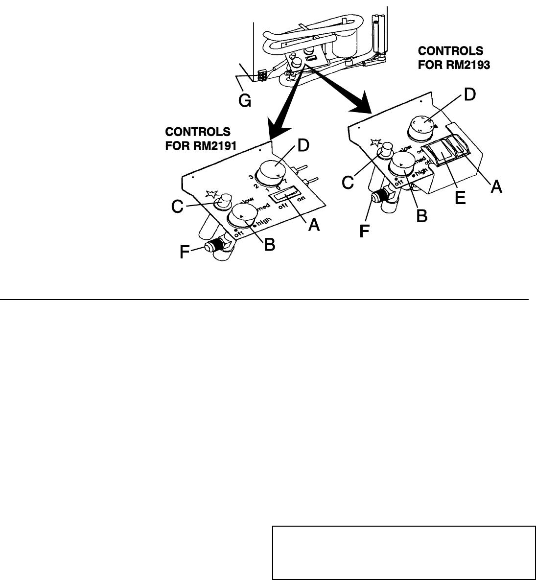
The gas and electric controls are located at the
rear of the refrigerator and are accessible through
the lower vent in the outside wall of the vehicle.
See FIG. 8.
FIG. 8
3. OPERATING INSTRUCTIONS
A. LP GAS OPERATION
After initial installation, servicing, or changing gas cylin-
ders, etc., the gas line may contain some air which should
be allowed to escape by briefly turning on the refrigerator
or other gas appliances. This will ensure that the flame
lights immediately. See FIG. 8 for control location and
identification.
1) Open the shutoff valve of the gas bottle. Check
that there is enough gas. Open any on-board
shutoff valve which is in the gas line to the refrig-
erator.
2) Open the lower vent at the rear of the refrigerator
on the outside of the vehicle, and switch the
electrical toggle switch/es (A in RM2191) and (A
and E in RM2193) to the "OFF" position.
3) Turn the gas thermostat control (B) to the highest
setting.
4) Depress the knob (B) of the flame failure device,
turn it to position "HIGH", and hold it down while
depressing the piezo igniter button (C) several
times in quick succession (a click should be heard
each time it is depressed).
5) Keep the knob depressed for a further 10-15
seconds.
6) Release the knob and check for flame by looking
through the opening in the metal burner cover.
7) If the burner has not lit, repeat the lighting proce-
dure. If the burner fails to light within a couple of
attempts, contact a qualified technician or your
dealer.
NOTE: The refrigerator has a flame failure device which
will automatically shut off the gas to the burner if the
flame is blown out. While the knob (B) is being held in,
this device is temporarily inoperative.
8) If the ambient temperature is above 80°F and/or
the door of the refrigerator is opened frequently
the knob should be left in the "HIGH" position.
9) To terminate gas operation, turn knob (B) to the
"OFF" position.
DO NOT attempt to operate the refrigerator by both gas
and electricity at the same time. Always ensure that
one method of operation is turned off before using the
alternate energy source.
A = DC ON/OFF SWITCH
B = GAS ON/OFF SAFETY VALVE
C = PIEZO IGNITOR
D = ELECTRIC THERMOSTAT
E = AC ON/OFF SWITCH
F = GAS INLET FITTING
G = DC TERMINAL BLOCK


