


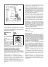
9. FLUE ARRANGEMENT
Flue Baffle
The flue baffle (4, fig. 10) must be in position in the central tube
of the boiler, suspended on its support wire so that the lower end
of the baffle is 75 mm (3") above the bottom of the central tube
over the burner. The top end of the baffle support wire is bent into
the shape of an "O" and rests horizontally on the tp of the central
tube. The baffle is correctly positioned during the manufacture
ans should not become displaced during normal use. If the flue
baffle is missins or is incorrectly located, the cooling unit will not
operate properly on gas. Any strapping tape used to retain the
baffle support wire to the top of the boiler casing during transit
should be removed before installation.
Flue Venting Kit
The flue gasses must be vented directly to the outside air. Only
the flue venting kit (supplied with the refrigerator in the United
Kingdom) is recommended for this purpose. It consists of the
following parts:
Flue Top Complete-G
Flue Outlet Cover Plate-B
Exhaust Gas Pipe Complete-F
Screw-sELF tAPPING. nO. 6 X 1/4in-H
The flue top (G) is in the form of a lazy "T" and incorporates an
air-break to minimise the possibility of flame extinction due to
draughts.
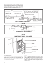
Leading from the flue-top, the extension tube (F) has to pass
through the wall of the vehicle to direct the flue gasses to the
outside. Care must be taken in determining the positions of the
centres of the holes in the inner and outer skins of the caravan
wall to accept the extension tube. As the amount of space
between the back of the refrigerator and the inside wall og the
vehicle as well as the thickness of the wall, may vary for each
type of caravan, it is not possible to give actual dimensions
therefore each case must be considered carefully before starting
to make the opening. Take particular care to ensure that the angle
is correct so that when in position, the extension tube will line up
accurately with the sloping part of the flue-top.
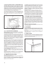
The opening mus be large enough to allow the insertion of a layer
of non-combustible material around the extension tube as shown
in fig. 7, but the opening in the outer skin must not exceed 70 mm
(2 3/4") in diameter, otherwise the flange on the flue outlet may
not cover it completely.
4
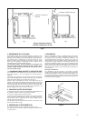
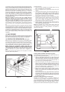
Alternatively, wooden battens may be screwed to the sides of the
recess, from front to back, bearing down on the top of the cabinet to
hold it firmly, as shown at A, fig. 4. Whichever method is used, it must
be possible to remove the refrigerator easily for subsequent servicing
purposes. The brackets or battens must be in a position where they
will not restrict the air circulation over the cooling unit; they must not
be positioned across the cabinet over the fins of the condenser of the
cooling unit at the rear, otherwise air-flow will be impaired and
performance affected.
Fitting the Upper Ventilator
To fit the upper ventilator, screw a block of wood approx. 25 mm (1")
square x 66 mm (2 5/8) long. to each side of the recess, 16 mm (5/8")
back from the front edge, as shown at B, fig. 4. Secure the ventilator
to the blocks with a screw through the hole provided at each end.
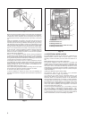
Additionnal Ventilator
To reduce the amount of heat entering the caravan, particularly when
used in warner climates, an additionnal ventilator (A, fig. 5), may be
fitted in the wall of the vehicle, preferably above the level of the top
of the refrigerator. (The exterior flue venting kit must still be used).
All surfaces above and adjacent to the flue outlet, and beside and
below the burner housing should be of, or protected by, metal or
other inflammable material.
8. VENT HOLE UNDER REFRIGERATOR
A ventilation hole of not less than 13 cm2 (2in2) effective area (40
mm or 1 5/8" diameter) must be provided in the floor below the
refrigerator as shown in fig. 5. The hole should lead directly to the
outside air through the floor or wall so that, in the event of a gas leak,
it would provide an escape outlet for the heavier-than air gas. It
should not be too close to the burner where draught could affect the
flame.
On mobile installations, the vent hole should be shielded against
entry of mud etc., by a deflector as shown in fig. 5a, fitted underneath
with its "closed" end facing the front of the vehicle. The deflector
should be made from a suitable piece of metal, to suit the particular
installation.
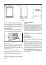
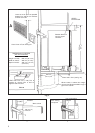
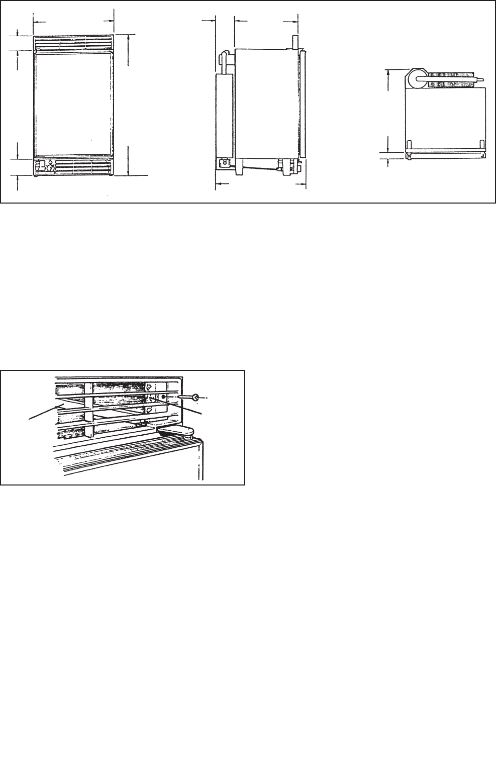
Fig. 3
Fig. 4
73 mm
(2
7
/
8
")
100 mm
(4")
300 mm
(11
13
/
16
")
39 mm
( 1
1
/
2
")
380 mm (15")
439 mm (17
5
/
16
")
510 mm (20
1
/
16
")
659 mm (25
15
/
16
")
400 mm
(15
13
/
16
")
A
B