


6
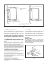
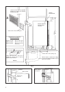
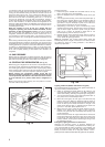
When the opening has been made in the caravan wall, the extension
tube (F) may need to be shortened to suit the particular installation.
To determine if this is necessary, fit the flue top (G) to the top of the
central tube of the boiler casing and secure it by means of the screw
(H).
Place the refrigerator into position, then insert the free end of the
extension tube through the wall of the caravan and over the outlet of
the flue-top as far as it will go. Measure the length 'X' (fig. 9) of any
tube protruding from the outside. Transfer this measurement to the
other end of the tube as shown at 'Y' (fig. 9) and cut at right angles
through the tube at this point to shorten the tube to the correct length.
Note 1. If the caravan wall is not vertical or is contoured in the vicinity
of the flue outlet, it may be necessary to make a packing piece from
metal or other non-combustible material, of a suitable shape to
ensure that, when in position, the plate on the flue outlet is parallel
with the back of the refrigerator.
Note 2. It is not advisable to lengthen the flue venting arrangement
for more than a short distance as this may result in the flue gasses
becoming prematurely cooled and water vapour (which is produced
during the natural process of combustion) condensing in the flue and
running back into the boiler insulation and burner.
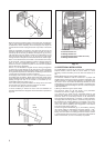
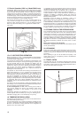
At this stage, refer to items 10 and 11 in order to prepare for the 12V
and bottled gas connections. When these have been made, before
finally positioning the flue extension tube (F), ensure that the portion
passing through the wall of the vehicle is surrounded by non-
combustible material as shown in fig. 7.
Use a soft sealing compound between the flange of the flue outlet
and the wall of the caravan to prevent ingress of rain water.
Fit the outer cover (B) by means of 4 screws.
It will be necessary to remove the outer cover and withdraw the
extension tube before the refrigerator can be moved out of position at
any time.
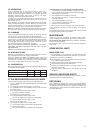
10. ELECTRICAL INSTALLATION
On model RM123, the boiler of the cooling unit is fitted with two
separate heaters, rated at 75W, for use on 230V a.c. mains
electricity, and the 12V battery in the car when the caravan is on
tow.
Model RM122 does not have a 230V heater fitted.
The electrical installation must be carried out in a proper and
durable manner, taking into account all relevant regulations and
codes of practice. For mains voltage operation, it is important that
the circuit to and in the caravan is effectively earthed. All mains
voltage wiring in the caravan must be installed in accordance with
current IEE Regulations including the use of an outlet and coupler
to BS 4343/CEE 17.
a) Wiring for Electronic Igniter (where fitted)
The electronic igniter for the gas burner is for permanent
connection to a 12V d.c. supply, e.g car battery.
In a motor-van, the igniter can be connected directly to the
vehicle's main battery or to an existing 12V circuit in the vehicle
which will remain on continuously and will not be switched off
when the engine is switched off. In a caravan, in order to maintain
the supply when the towing vehicle is unhitched, the igniter must
be connected to an auxiliary battery in the caravan. The current
drain of the igniter is negligible therefore the battery can be one
that is also used for operating other equipment in the caravan
such as the water pump, lights, etc.
Connect the igniter terminal block (fig. 11) to the battery, ensuring
that correct polarity is observed-the terminals marked' + and'-'
must be connected to the similarly marked terminals of the
battery. The wire used for connecting should be at least 0,5 mm2
in cross-sectional area and a 0.5 or 1.0 amp inline fuse should be
fitted in the feed wire, as near to the battery as possible.
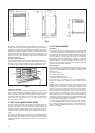
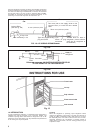
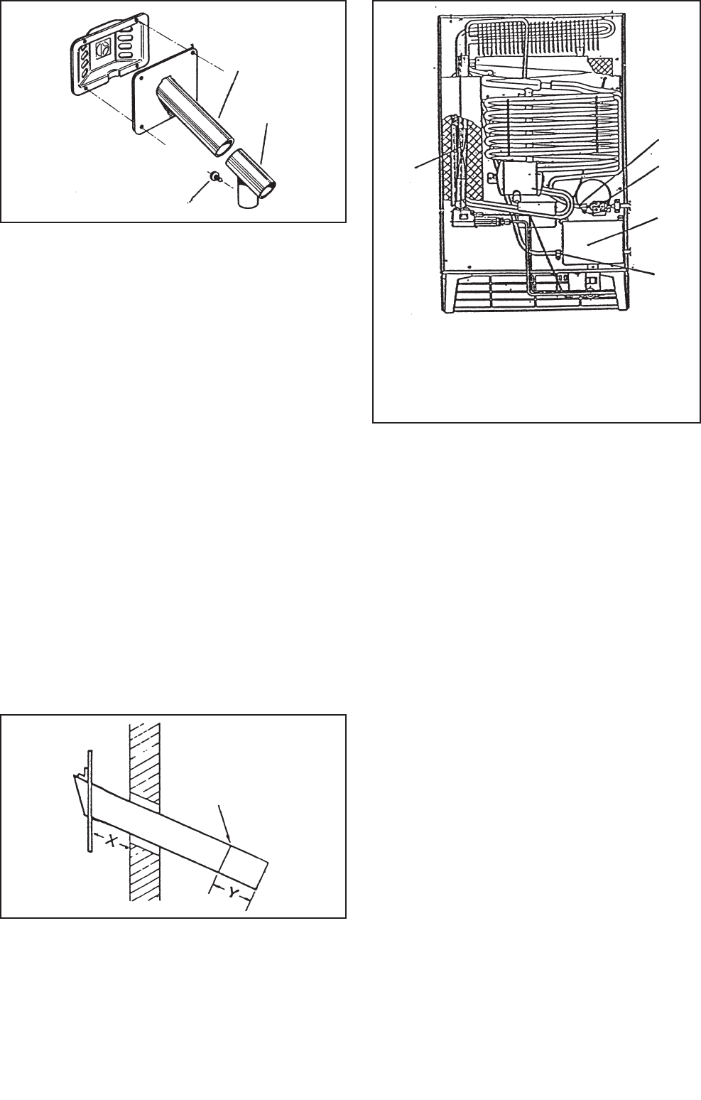
Fig. 8
Fig. 9
Fig. 10
1.Flue Baffle.
2.Therminal block 12 V.
3.Heating element 12 V.
4.Therminal block 230 V (under the cover).
5.Heating element 230 V.
F
G
1
3
2
4
5
H
CUT
HERE