


7
b) Mains Voltage Connection
For connection to a 230V electricity-supply, the refrigerator has a 3-
core mains lead which is intended for connection to a oroperly
earthed plug and socket outlet. The socket outlet should be fitted in
the caravan in a position readily accessible to the user, within reach
of the mains lead. In the United Kingdom, the plug and socket outlet
should be of the non-reversible type.
IMPORTANT: The wires in the mains lead of this appliance are
coloured in accordance with the following code:
GREEN AND YELLOW = EARTH.
BLUE = NEUTRAL.
BROWN = LIVE.
As the colours of the wires may
not correspond with the
coloured markings identifying
the terminals in your plug, in
the United Kingdom, proceed
as follows:
Green and Yellow, 3 AMP
FUSE, E, N, Lrown, Coro
Clamp.
The wire which is coloured
GREEN AND YELLOW must
be connected to the terminal in
the plug which is marked with
the letter E or by the earth
symbol or coloured green
or green and yellow.
The wire which is coloured BLUE must be connected to the terminal
which is marked with the letter N or coloured black.
The wire which is coloured BROWN must be connected to the
terminal which is marked with the letter L or coloured red.
WARNING-THIS APPLIANCE MUST BE EARTHED
In the United Kingdom, the plug or circuit to the refrigerator must be
fitted with a fuse not greater than 5 amps. If a 13 amp (BS 1363)
fused plug is used, it should be fitted with a 3 amp fuse. In other
countries the fuse rating will depend upon the voltage and local
practice.
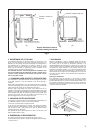
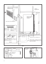
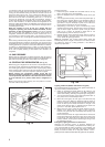
c) Wiring for 12V Operation (See figs. 10, 12a and 12b).
For operation on 12V, the boiler of the cooling unit is fitted with an 75
watt heating element (2, fig. 10) connected to a terminal block (3)
attached to the back of the refrigerator. Before installing the
refrigerator, the wiring for the 12V supply should be connected to the
terminal block, leaving enough slack subsequent insertion and
withdrawal of the refrigerator for servicing purposes.
The wire used for connecting must be at least 2 mm2 in cross-
sectional area (e.g. 28/030 mm) and should be kept as short as
possible. Polarity is not important therefore is does not matter which
way round the two wires are connected to the terminal block on the
refrigerator.
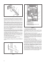
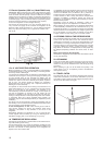
A suitable size switch or plug and socket should be fitted in a
convenient position in the wiring in the caravan so that the
refrigerator can be readily disconnected from the 12V supply
when 12V operation is not required, see fig. 12a.
To prevent undue voltage drop (which would impair the
performance of the cooling unit) the wiring for the 12V refrigerator
supply should be connected directly to the terminals of the main
battery in the towing vehicle and not to an auxiliary battery in the
car or caravan. Existing wiring in the car should not be used for
the refrigerator supply as this would normally be intended for a
different purpose and may not be capable of carrying the 7 amp
(min.) load of the refrigerator satisfactorily.
The chassis or body of the caravan should not be used as a
substitute for one of the wires otherwise voltage drop is almost
certain to occu either now or later on. The body of the car can,
however, be used in place of one of the wires for the 'earth' return
but the connection to it must be well made, with paint, grease,
etc., removed from the area of contact and it should be located in
a position protected from the weather, such as inside the boot.
A 15 amp, continuous rating, fuse must be incorporated in the
supply to the refrigerator, as near to the battery as possible. A
good quality fuse holder should be used having adequate size
well-made contacts which will carry the current load without
undue resistance.
When operating on 12 volts, the refrigerator has a relatively high
current consumption (7 amps) and it is only intended to be used
by this method of operation whilst the engine is running and
charging the battery otherwise the battery may become
discharged to a point where it will not re-start the car engine, 12
volts operation is not thermostatically controlled and the 75 watts
heater is 'on' all the time the refrigerator is connected ti the 12V
supply and any switches in the line are 'on'.
Note: to minimise the possibility of a drained battery due to the
refrigerator being inadvertently left operating when the engine is
at rest, it is strongly recommended that a suitable relay device is
fitted in the car, in circuit with the ignition switch, so that when the
engine is switched off, the refrigerator is automatically switched
off-see Fig. 12b.
11. GAS CONNECTION
The gas installation should only be carried out by a person
experienced in gas fitting.
It is recommended that the gas pipe feeding the refrigerator is run
underneath the caravan and is so arranged that it is possible to
turn off the supply to all appliances other than the refrigerator
when they are not required. The supply pipe should preferably be
of copper; if any other material is used, it must of a type approved
for use with continuously operating bottled gas appliances and
have threaded connections throughout. Push-on connections
must not be used. (We do not recommend the use of "rubber"
type flexible tubing for connecting permanently operating
appliances of this type in the United Kingdom).
All connectors, etc., should be of a type specifically designed for
the connection pipe used. Screwed joints should be sealed with
a jointing compound approved for use with bottled gas.
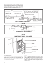
The gas supply pipe should be connected to the 1/8" B.S.P.
female inlet adaptor (located underneath the refrigerator) by
means of a suitable threaded coupling - see note below. The inlet
adaptor will accept a 1/8" B.S.P. male thread. (Access to the inlet
adaptor may be obtained by pulling off the knob of the gas control
valve then removing the lower ventilator by taking out the screws
at the ends).
Depending ont the location of the gas supply pipe, it may be
necessary to connect a piece of cooper pipe to the inlet adaptor
on the refrigerator before placing the refrigerator in the recess.
This pipe should be of suitable length and pre-shaped so that,
when the refrigerator is in place, the end of the pipe will be in a
convenient and accessible position for connection to the main
gas supply or to another piece of pipe coming from the main gas
pipe.
In making the connection to the refrigerator, it is recommended
that a union gas cock of an approved type for bottled gas is
incorporated in the supply line a position which is readily
accessible to the user. For eventual servicing purposes, the union
should be on the outlet side of the cock and the pipework should
be positioned so as not to prevent the refrigerator from being
readily withdrawn.
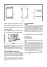
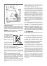
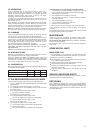
Fig. 11
View of bottom of refrigerator showing electronic
igniter layout
Burner housing
Bottom of refrigerator
Iigniter
switch
Igniter
terminal
block
Housing for
electronic
components