


Electrolux Professional S.p.A.
Ovens Platform Customer Support
Technical Training & Service
AOS_Q OVENS – Service manual
(593804600 - ENG)
File: AOS ONE service manual (ENG).01.doc ©Copyright 2007 by Electrolux Professional P.14/31
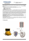
The gas system is made with CO and NO
x
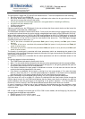
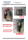
low emission burner. The main components are the following:
gas valve from SIT type SIGMA 848
AC burner blower that is intaking air through a calibrated mixer where the air–gas mixture is created;
then the fun conveys the mixture to the burner
A cavity and a boiler heat exchanger made with a corrugated tube for increasing the efficiency
An ignition rod and a detection rod
A flame control device
An external igniter
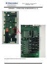
Starting a cooking cycle, the POW board of the oven activates the flame control device and the burner fan
whose speed is controlled with a PWM signal.
The POW board activates the flame control device. From pin 8 of this device a high voltage output (230 Vac)
is carried to the relevant burner fan and to the high voltage digital input section of the POW board (X10/5÷8).
With an high voltage input on X10/5÷8, the POW board generates on X9/2÷5 a PWM signal to control the
speed of the burner fans (a signal that defines the rotating speed of he fan and so the quantity of sucked air
and gas) and the 12 Vdc on X9/1 to feed the inner board of the burner fan. The PWM signal changes
according to the status of the burner, i.e.:
Start of the burner: controlled with parameters StcA (start of cavity burners) and Stbo (start of boiler
burners).
Full power of the burner: controlled with parameters FucA (full power of cavity burners) and Fubo (full
power of boiler burners)
Half power of the burner: controlled with parameters hAcA (half power of cavity burners) and hAbo (half
power of boiler burners)
The quantity of sucked gas is controlled with those parameters (which are determining the speed of the
burner fans), with the injector/diaphragm inserted at the outlet of the gas valve and with the calibration of the
offset value on the gas valve.
The quantity of sucked air is controlled with the above parameters and with the calibrated aerator on the
mixer.
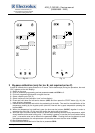
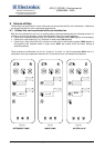
The ignition sequence is then the following:
• The POWER board activates the flame control device
• After 1.5 s, the control device activates the fan that start at the speed determined with parameters Stxx
• The flame control device activates the external igniter through pin 14, the igniter generates the spark for
2s and after these, there are 2 s for flame detection
• If the flame is detected, the start speed is maintained for around 10 s and after this time the fans are
carried to their working speed (half or full power)
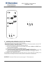
• If the flame is not detected, the fan keep on running for an inter purge phase of 15 s; after this phase
there is a stop of the fan for 1 s and the ignition sequence is repeated. If the flame is still not detected
there will be again 15 s of purging phase and this for five times before the lockout signal.
In case of loosening of the flame signal during working, only one re-ignition attempts takes place.
So if the burner fan is off for at least 0.5 s (the fan is controlled from the flame control device through the
230Vac signal form pin 8), the POW board deduces that the flame control device is going to try again an
ignition sequence and then goes back to the beginning of the ignition sequence. If on the contrary the
burner fan is off for at least 5 s, the POW board deduces that the flame control device is in lockout.
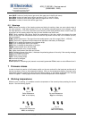
In case of conversion to different type of gas, besides the injector/diaphragm also the parameters, which
control the PWM signal, and the offset pressure calibration have to be changed according to the gas
calibration table
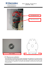
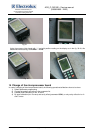
NB: In case of changing from natural gas to LPG or G30 in some models, the fan flange (fig. 24) has to be
changed; these changes has to be made in
• CAVITY burner of 10 2/1 e 20 2/1 ovens
• BOILER burner of 10 1/1, 10 2/1 e 20 1/1 ovens