


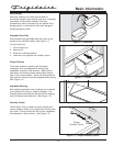
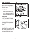


Operation of Electrical Control Components
Freezer and Refrigerator Modules
The modules, when selected by the rocker switch, control the temperature of the unit by an internal thermistor
mounted on the circuit board. Each module has an individual service mode.
Each module has the following connections to the rear of the circuit board:
1= Neutral
2= Not Used
3= L1
4= Compressor
5= Defrost Thermostat
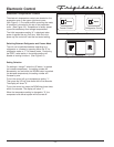
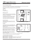
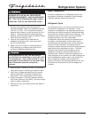
DPDT Rocker Switch
The DPDT Switch is connected to the household power
supply with L1 connecting to terminal 2, and the Neutral
line to terminal 5. (See Figure 3-3)
In refrigerator mode, The DPDT switch will have the a
closed condition between terminals 5&4, and 2&1.
In freezer mode, The DPDT switch will have the a
closed condition between terminals 5&6 and 2&3.
Ambient Thermostat
The ambient thermostat will close at 35°F (1.6°C) and
will then supply power to terminal 6 of the fan relay.
(See Figure 3-4)
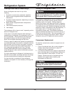
Fan Relay
The purpose of the fan relay is to direct power to the
auxiliary heater and fan motor when ambient temperatures
go below 35°F (1.6°C) and the DPDT switch has
refrigeration selected.
Use an ohmmeter to test the fan relay. The following
conditions should result with the fan relay in the OFF state:
Between terminals 7 & 8 should read 4.4k Ohms.
Between terminals 6 & 2 and 5 & 1 - closed condition.
Between terminals 4 & 6 and 3 & 5 - open condition.
When voltage is supplied to terminal 6 through the
ambient thermistor, voltage will come out terminal 2
and connect with terminal 1.
Terminal 1 is connected to terminal 5 which feeds power to the evaporator fan motor.
The following conditions should result with the fan relay in the ON state:
Line voltage is supplied to terminals 7&8.
Between terminals 4 & 6 - closed condition.
Between terminals 6 & 2 - open condition ( cutting power to the auxiliary heater).
Between terminals 3 & 5 - closed condition (supplying line voltage to the fan).
Between terminals 5 & 1 - open condition
2-3
Electronic Control
1
2
3
4
5
6
7
8
L1
Nuetral
DPDT
Switch
Figure 3-4. Fan Relay Terminal Arrangement
Figure 3-3. DPDT Switch Arrangement