


7
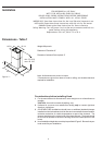
Installation
Wiring to Power Supply
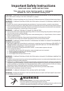
WARNING!
ELECTRICAL GROUNDING INSTRUCTIONS
THIS APPLIANCE IS FITTED WITH AN ELECTRICAL JUNCTION BOX WITH
3 WIRES, ONE OF WHICH (GREEN/YELLOW) SERVES TO GROUND THE
APPLIANCE. TO PROTECT YOU AGAINST ELECTRIC SHOCK, THE
GREEN AND YELLOW WIRE MUST BE CONNECTED TO THE GROUNDING
WIRE IN YOUR
HOME ELECTRICAL SYSTEM, AND IT MUST UNDER NO CIRCUMSTANCES
BE CUT OR REMOVED.
Warning: Turn off power circuit at the service panel before wiring this unit.
120 VAC, 15 or 20 Amp circuit required.
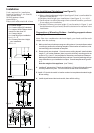
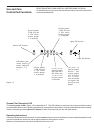
16. Remove j-box cover as shown in Figure 10.
17. Remove the knockout and install the strain relief (conduit) connector (1/2") in
junction box.
18. Run 3 wires; black, white and green (#16 AWG) in 1/2" conduit from service panel
to junction box.
19. Connect black wire from service panel to black or red in junction box, white to
white and green to green-yellow. See Figure 10.
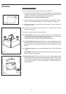
20. Close junction box cover, check all light bulbs to make sure they are secure in
their sockets, then turn power on in service panel and check lights and blower
operation per Care & Use section of this manual and install filters.
Final assembly
For final Chimney Cover installation, DO NOT USE ELECTRIC SCREW
DRIVER.
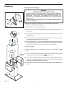
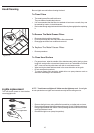
21. Fit the nuts with fixing hooks supplied
inside the top and bottom sections of the
chimney covers at all the rectangular slots. Figure 11-12.
22. Join the two top sections of the chimeny covers to cover the chimney structure.
Screw the two sections together with 4 screws (2 each side- see the plan
diagram for joining the two sections). Figure 11.
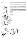
23. Fix the covers to the structure, near the ceiling, with two screws (one each side).
Figure 11.
Figure 10
Figure 11
Nut
rear
Chimney
cover
front
Chimney
cover
Top
chimney-to-structure
fixing point