


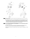

GAS LINE CONNECTION
WARNING: Only persons licensed to work with gas piping may make the necessary gas connections to this appliance.
GAS LINE CONNECTION
• This stove is equipped with a 3/8” female NPT thread located on the right hand side of the gas valve. Consult your local
authorities codes or the CAN/CGA B 149 (1 or 2) installation code in Canada, or in the USA gas installations follow either
local codes or the current edition of the National Fuel Gas Code ANSI Z223.1.
• The efficiency rating of this appliance is a product thermal efficiency rating determined under continuous operating
conditions and was determined independently of any installed system.
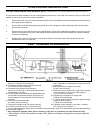
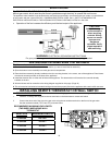
The gas line can be brought into the unit from either the left or the right side of the appliance. It is more convenient to bring the
gas line in from the right side as this will allow optional fan installation and service if required.
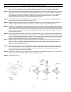
• The appliance and its shutoff valves must be disconnected from the gas supply piping system during any
pressure testing where the pressure exceeds 1/2 PSIG (3.45 kpa) or damage will occur to the valve.
The appliance must be isolated from the gas supply piping system by closing its individual manual shutoff valve during any
pressure testing of the gas supply piping system at test pressures equal to or less than 1/2 psig (3.5 kPa).
Always check for gas leaks with a soap and water solution after completing the required pressure test.
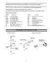
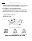
TO TEST VALVE PRESSURES
• The pressure taps are located on the left side of the valve
• Turn set screw 1 turn counter clockwise to loosen,.
• Place 5/16” (8 mm) I.D. hose over pressure tap system.
• Check pressures using a manometer.
• When finished, release pressure, remove hose & tighten set screw.
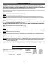
Pilot Adjustment Screw
Gas Control Knob
Hi Low Knob
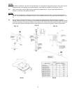
ORIFICE SIZES, PRESSURES AND BTU’S
ALL MODELS ARE EQUIPPED WITH A VARIABLE OUTPUT GAS CONTROL.
NATURAL PROPANE
FRONT BURNER:
#48 DMS #56 DMS
REAR BURNER:
#50 DMS #57 DMS
Manifold Press:
3.8” wc / 0.95 kpa 11.0” wc / 2.74 kpa
Min. Manifold Press:
1.1” wc / 0.27 kpa 2.7” wc / 0.67 kpa
Max. Supply Press:
7.0” wc / 1.74 kpa 12.0” wc/ 2.98 kpa
Min. Supply Press:
5.0” wc / 1.25 kpa 11.5” wc / 2.86 kpa
Max. BTUH Input:
30,000 Btu/h/ 8.8 KW 30,000 Btu/h/ 8.8 KW
Min. BTUH Input:
15,000 Btu/h/ 4.39 KW 15,000 Btu/h/ 4.39 KW
Output
Fan on, 22,050 Btu/ h/6.46 KW Fan on, 22,350 Btu/h/ 6.55 KW
Fan off, 21450 Btu/h/.6.28 KW Fan off, 21750 Btu/h/ 6.37 KW
NEVER USE AN OPEN FLAME FOR LEAK TESTING
Inlet Pressure Tap
Manifold Pressure Tap
18