


ELECTRICAL
The ENVIROGAS EG 22.Z/CLEARANCE .DV. will operate with no external power supply. These models have a
Millivolt gas control which uses the pilot flame to generate enough electricity to operate the main burner.
The appliance when installed, must be electrically connected and grounded in accordance with local codes or in the absence
of local codes, with the current CSA C22.1 CANADIAN ELECTRICAL CODE. Part 1, SAFETY STANDARDS FOR
ELECTRICAL INSTALLATIONS, or THE NATIONAL ELECTRICAL CODE ANSI / NFPA 70 in the USA.
• Operation of the fan increases the efficiency and the heat output of the appliance.
WARNING: ELECTRICAL GROUNDING INSTRUCTIONS.
For your protection against electrical shock, this unit should be properly grounded.
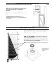
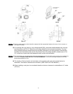
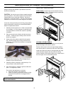
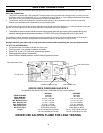
INSTALLING OR REMOVING THE BLOWER
The blower does not require lubrication.
1. Turn the unit off and make sure the unit is cool before you start to install the fan assembly.
2. Open the bottom louver assembly to access gas control compartment.
3. Place the blower assembly already installed on the fan-mounting bracket, in the center, rear of the appliance. Place blower
over the two screws provided on the base of the appliance.
4. Install the electrical box on either the left side of the appliance. This electrical box will have the fan controller already
installed on the box.
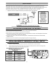
5. Wire the blower and fan controller to the wiring diagram supplied on this page. (Page 19)
6. This unit must be hard wired to household wiring and should be properly fixed to the appliance with a stain relief connector.
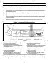
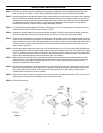
INSTALLING REMOTE THERMOSTAT OR WALL SWITCH
RECOMMENDED WIRE SIZE for thermostat installation: 18 gauge, 2 wire solid core, Low Voltage wire. (Bell wire)
1. Install the 18 Gauge wire supplied to the two terminals on the thermostat or remote wall switch.
2. Connect the other end of the wire to the gas valve using the two outside terminals on the front of the gas valve.
Use the terminals marked (TP/TH and TH) as shown below.
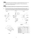
RECOMMENDED MAXIMUM LEAD LENGTH
(TWO WIRE) WHEN USING WALL
THERMOSTAT
WIRE SIZE MAXIMUM LENGTH
14 GAUGE 100 FEET
16 GAUGE 64 FEET
18 GAUGE 40 FEET
20 GAUGE 18 FEET
CAUTION
Label all wires prior
to disconnection
when servicing
controls. Wiring
errors can cause
improper and
dangerous
operation. Verify
proper operation
after servicing.
19