


3 90846
INSTALLATION
WARNING: Only qualified personnel should service internal components or electrical
wiring.
LOCATION
Locate the icemaker/dispenser indoors in a well ventilated area. Avoid exposure to direct sunlight and/or heat
caused by radiation. Ambient room temperature must be in the range of 60° to 90° F. Do not install unit in an
enclosed area where heat build-up could be a problem. For proper air flow for the refrigeration system, allow 6”
clearance at the back of the unit and a 12” clearance at the right side panel.
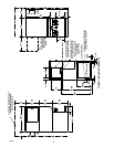
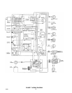
Consult Figure 3 for utility connection locations.
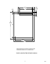
Consult Figure 2 for dimensions for mounting unit to the counter with the hardware provided. NOTE: that the
unit must be level for proper operation.
The unit must be sealed to the counter. The MOUNTING TEMPLATE drawing (Figure 2) indicates the openings
which must be cut in the counter. Locate the desired position for the unit, then mark the outline dimensions and
cut-out locations using the template drawing. Cut openings in counter.
Apply a continuous bead of NSF International (NSF) listed silastic sealant (Dow 732 or equal) approximately
1/4” inside of the unit outline dimensions and all around all openings. Then, position the unit on the counter with-
in the outline dimensions. All excess sealant must be wiped away immediately.
PLUMBING
Connect the icemaker to a cold, potable water source, suitable for drinking. This water source must comply with
the basic plumbing code of the Building Officials and Code Administrators International Inc. (BOCA) and the
Food Service Sanitation Manual of the Food and Drug Administration. Do not install unit on a water softener
line. It is recommended that a hand shut-off valve and strainer be used on the incoming supply line. A 1/4” out-
side diameter for the water supply hook up (See Figure 3). For proper operation of the incoming water supply
pressure must be in the range of 30-90 PSIG. Install a pressure regulating valve if above this range!
IMPORTANT: To insure proper icemaker operation and also to reduce the frequency of water-related
service problems, a water filter should be installed. REMCOR recommends the use of IMI Cornelius
filter, model number 81COR01PS.
For specific recommendations on these filter systems for your local water conditions, consult with a distributor in
your area or contact the filter manufacturer.
Connect two (2) 3/4” IPS (or equal) drain lines to the 3/4” threaded drain connections at the lower rear of the
unit. These lines must pitch downward to and open drain and must contain no traps, or improper drainage will
result. All drain connections must be in accordance with the basic plumbing code of the Building Officials and
Code Administrators International (BOCA) and local codes.
NOTE: In areas where consistently warm water temperatures are encountered, the use of a pre-cooler
in the water line is recommended to maximize the ice production of this unit.
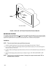
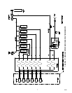
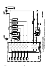
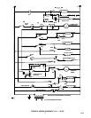
ELECTRICAL (see figure 1 )
A 4 X 2 junction box is located at the rear of the unit for the supply hook-up. Connect the icemaker to its’ own
individual circuit per the National Electric Code and Local Code (see SPECIFICATIONS for ampacity and fuse
size).
IMPORTANT: The wire size must be adequate for the ampacity rating and the supply voltage must be
within a range of ± 10% for proper icemaker operation.
NOTE: That the unit requires a 2-wire systems plus earth ground for proper operation.