13
6. Once proper draft is achieved, measure CO2 and smoke level. If necessary, adjust the intake airflow at the burner
to obtain the highest possible CO2 reading with a zero smoke reading. As the intake airflow is increased or
decreased, the draft may change. Repeat steps 3 through 6 to re-adjust the draft control and choke plate before
attempting any other adjustments.
7. Measure combustion efficiency and exhaust gas temperature at the venter inlet. Combustion efficiency should be
adjusted to maximum attainable at zero smoke. Exhaust gas temperature at the venter inlet should range between
200ºF and 550ºF.
8. If maximum efficiency and zero smoke yields a temperature below 200ºF at the inlet to the venter, the following
suggestions must be considered.
A. Use a larger oil nozzle or higher oil pump pressure to raise the firing rate of the burner. Repeat
steps 3 through 7 until all combustion parameters are within the specified ranges.
B. Reduce the length of the duct from the appliance to the venter which will increase the venter
inlet temperature.
C. Insulate the vent pipe to minimize heat loss.
D. Seal the vent pipe joints to reduce uncontrolled dilution air.
TESTING:
1. The thermostat (wall thermostat, or aquastat) calls for heat, starting venter motor.
2. After the venter motor has come up to speed, the pressure switch closes. This closes the circuit to the burner and
allows the burner to operate. This occurs in approximately 1 to 2 seconds.
3. After the heating requirement is satisfied, the thermostat circuit opens and deactivates the burner and power
venter circuit.
4. Oil venting systems require a post purge device. During the post purge cycle, the venter operates for a period after
the burner has shut off. This is to purge the remaining flue gases and to cool the combustion chamber. Typical post
purge times are 3 to 5 minutes. Longer purge times may be required depending on system installation.
ANNUAL MAINTENANCE:
1. Motor: Inspect the motor once a year; it should rotate freely.
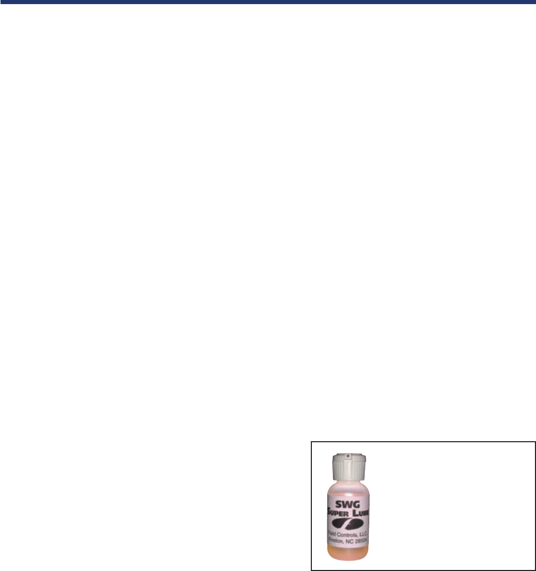
To prolong the life of the motor, lubricate with six drops of
SWG Super Lube, Part #46226200, annually. Use of any
other type of lubricant may cause premature motor failure.
2. Wheel: Inspect the venter wheel annually to clear any soot,
ash, or coating which inhibits either rotation or air flow.
Remove all foreign materials before operating.
3. Vent System: Inspect all vent connections annually for looseness, for evidence of corrosion, and for flue gas leakage.
Replace, seal or tighten pipe connections if necessary. Check the venter choke plate to ensure it is secured in place.
Check the barometric draft control to ensure the gate swings freely.
4. System Safety Devices: With the heating system operating, disconnect the pressure sensing tube from the pressure
switch on the CK Kit. This should stop the burner operation. Re-connecting the tube should relight the burner.
System Setup and Maintenance
• Oil motor and fan shaft with
SWG Super Lube annually
• Works in conditions of -40° to
300° (F)
• Synthetic lubricant which
maintains specified viscosity
• Use of any other lubricant may
cause premature failure
SWG Super Lube
7137FCHVentGuideOil_New:7137FCHVentGuideOil 5/8/08 10:45 AM Page 13
