


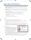

Table 3
10
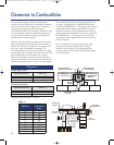
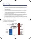
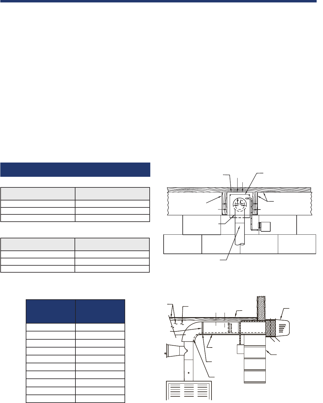
Clearance to Combustibles
If mounting the venting system near combustible
materials, refer to Diagram A for allowable installation
clearances. Clearances are based on an installation
using single wall galvanized steel vent pipe. If
manufactured double wall vent pipe is required or used
for the installation, clearance should be based on the
vent pipe’s rated clearance. Always check local code
requirements for code restrictions.
Routing of the vent system and clearances for the vent
pipe may be planned once the termination location is
determined. Route the vent pipe from the appliance to
the venter using as few elbows as possible. The
horizontal section of the vent pipe should have a slight
upward slope from the appliance to the venter. The vent
pipe size (diameter) can be smaller than a typical
chimney vented system and still overcome the higher
pressure losses because the power venter mechanically
creates the required draft or air flow to vent the system.
For estimating the minimum vent pipe diameter for an
oil system, multiply GPH by 140,000 BTU/GAL, then
divide by 12,600 BTU/sq. in. This will give the minimum
cross sectional area required. (See Table 3 for area to
diameter conversion.) For multiple equipment venting
systems, divide the total BTU/hr. input for all appliances
by 9,300 BTU/sq. in. This will give you the minimum
vent pipe diameter needed for the common breaching
of the vent system.
As a rule of thumb, size the vent pipe to the outlet
diameter of the heating equipment for a single
appliance venting system. For multiple appliance
venting systems, use the outlet diameter of the largest
unit and add 50%.
SQUARE HOLE
THROUGH WALL
COMBUSTIBLE
MATERIAL
METAL LINING FOR
550°F-400°F INPUT TEMP.
FLOOR JOIST
B-VENT
INPUT TEMP.
LOCATION
ELBOW
A
A
A
B
B
B
COMBUSTIBLE
MATERIAL
FLOOR JOIST
FLOOR
OUTER PIPE
EXTENSION
END PIPE COVER
SWG SERIES
POWER VENTER
BLOCK
FOUNDATION
FROM SWG UNIT
B-VENT or
L-VENT
ELBOW
INPUT TEMP.
LOCATION
A
B
Single Pipe System
Double Pipe System
Diagram A
Pipe Size
Nominal
Cross-Sectional Area
Sq.Inches
3" 7
4" 13
5" 20
6" 28
7" 38
8" 50
9" 64
10" 79
12" 113
14" 154
Allowable Inlet Temperature
Clearance (B)
400ºF or Less 3" min.
550ºF or Less 4" min.
550ºF or Less 3" min.*
Allowable Inlet Temperature
Clearance (A)
400ºF or Less .5" min.
550ºF or Less 1" min.
550ºF or Less .5" min.*
* With galvanized sheet metal liner or equivalent
7137FCHVentGuideOil_New:7137FCHVentGuideOil 5/8/08 10:45 AM Page 10