


9
Locating The Power Venter
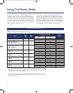
Procedure
1. Determine the total equivalent feet for each type of fitting
used in the venting system from Table 2.
2. Calculate the total feet for the straight lengths of pipe.
3. Add the equivalent feet of the fittings to the total amount of
feet of straight length pipe. This will approximate the total
equivalent feet of the vent system.
Example: System Pipe Size = 4"
Step 1 2-90° Elbows (4") = 14 Ft.
Step 2 10-2 Ft. Lengths of 4" Pipe = 20 Ft.
Step 3 Total Equivalent Feet = 14 Ft. + 20 Ft. = 34 Ft.
To estimate the equivalent foot length of the Reducer/Increaser chart, find
the figure at the intersection of the small pipe size and the large pipe size.
Table 2
Calculating Equivalent Feet of a Vent System
* 10" or larger should be 10’ minimum above public walkway.
** 10" or larger should be 4‘ above finished grade.
Using a Reducer/Increaser
Small Pipe Size
3" 4" 5" 6" 7" 8" 9" 10" 12" 14"
3" 0
4" 2 0
5" 4 2 0
6" 5 4 2 0
7" 6 5 4 1 0
8" 7 7 6 3 2 0
9" 7 8 7 5 4 2 0
10" 8 8 8 6 6 4 2 0
12" 8 10 10 8 9 8 6 4 0
14" 9 10 12 10 12 11 9 8 3 0
16" 9 11 12 11 14 13 13 11 8 3
18" 9 11 13 12 15 15 15 14 11 7
20" 9 12 14 13 16 17 17 17 15 11
Large Pipe Size
Vent Pipe
Fittings
Vent Pipe Diameter
3" 4" 5" 6" 7" 8" 9" 10" 12" 14"
Tee
19 25 31 38 44 50 56 63 75 89
Y-Connection
10 13 16 20 23 26 29 32 39 45
90° Elbow
5 7 9 11 12 14 16 18 21 25
45° Elbow
3 4 4 5 6 7 8 9 10 13
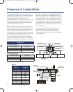
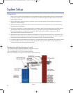
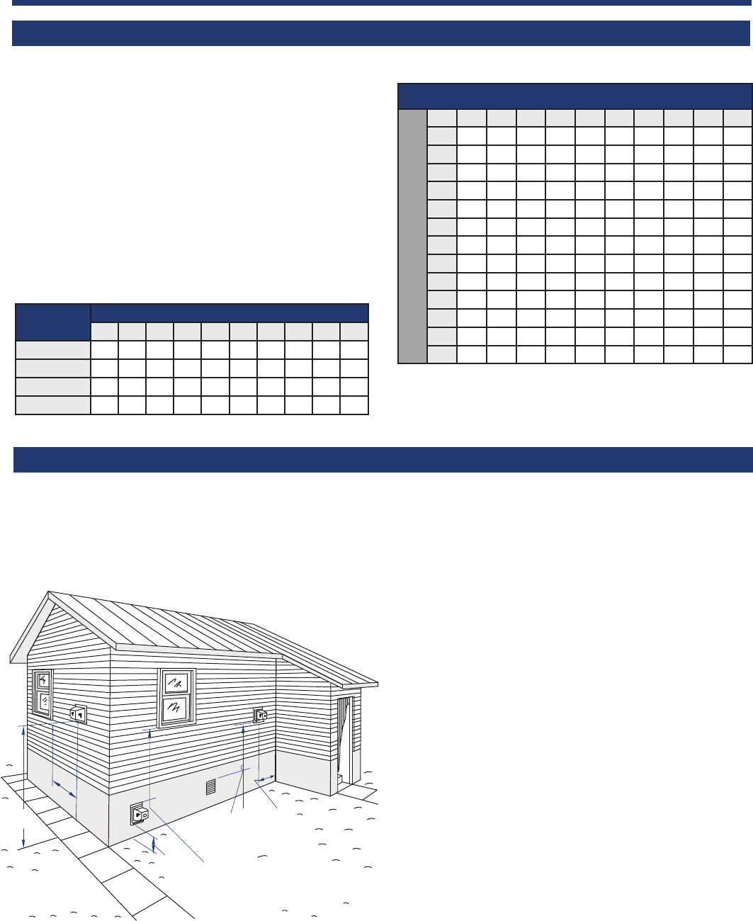
Terminal Locations of a Vent System
A
B
D
B
C
F
A. The exit termination of a mechanical draft system
must not be less than 7’ above grade when located
adjacent to a public walkway.*
B. The venting systems, with the exception of direct vent
appliances, must terminate at least 4’ below, 4’
horizontally, or 1’ above any door, window or gravity
air inlet into the building.
C. A venting system must terminate at least 3’ above any
forced air inlet located within 10’.
D. The bottom of the vent terminal must be located at
least 1’ above finished grade.**
E. The vent termination should not be mounted directly
above or within 3’ horizontally from an oil tank vent
or gas meter (not shown in diagram).
F. The vent termination point must not be installed closer
than 3’ from an inside corner of an L-shaped structure.
G. For basement installations where a window well must
be used or in installations where the vent terminal
cannot be mounted to maintain the minimum 12"
clearance above grade, use a Field Vent Riser™. The
Vent Riser ensures the vent termination is above grade
or the snow line and is in compliance with local codes
(not shown in diagram).
Location of the termination of the venting system should
comply with the National Fuel Gas Code, ANSI Z223.1,
manufacturer’s recommendations and/or applicable local
codes. See diagram for typical terminal locations.
7137FCHVentGuideOil_New:7137FCHVentGuideOil 5/8/08 10:44 AM Page 9