


Page 12
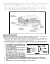
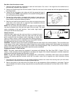
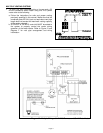
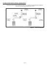
Diagram G – Multiple Wiring with two 24 VAC Appliances
2. To vent two 24 VAC appliances using one PVU power venter refer to the following.
a. Follow the instructions for safe and proper venting previously specified in this manual. Make sure that the
combined gross BTU/Hr input and equivalent vent pipe length does not exceed the maximum venting capacity of
the venter selected.
b. A CK-41 Control Kit must be added to the system to properly control the venter when common venting an
additional 24 VAC furnace or boiler. Tee the draft tube on the PVU unit to connect to the air pressure switch on
the Control Kit. Refer to Diagram G for wiring instructions.