


Page 6
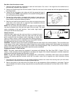
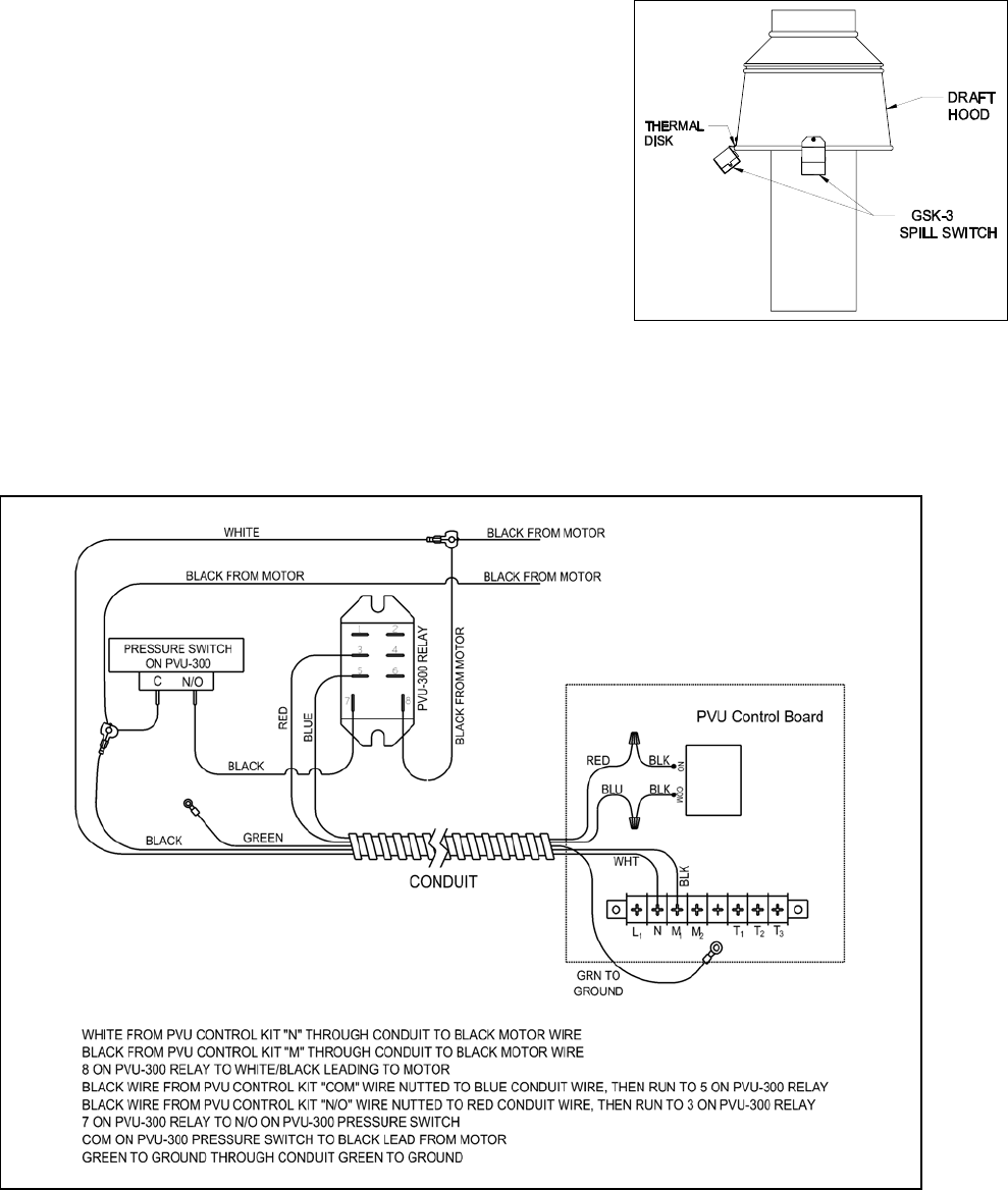
OPTIONAL GSK-3 EXHAUST GAS SPILLAGE DETECTOR SWITCH INSTALLATION
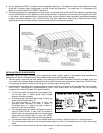
NOTE: Installation of the GSK-3 secondary safety switch is recommended
for LP and Natural gas fired appliances with a draft hood. This switch will
detect exhaust gas spillage out of the draft hood due to a blocked vent
system and/or inadequate draft during operation. When this switch senses
spillage it interrupts the power supply to the gas valve which terminates the
burner operation.
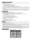
1. Mount the GSK-3 on the lower edge of the draft hood with the exposed
thermal disk directed into the draft hood (See Figure 7)
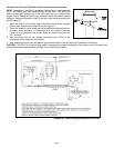
2. Route the electrical wires along the heating appliance cabinet within an
accepted wiring enclosure in accordance with the National Electrical
Code and any applicable local codes. Keep the wires away from any
HOT surfaces.
3. Wire the switch into the low voltage thermostat circuit. Refer to the
appropriate wiring diagram in this manual.
4. After installation, check the amperage through the thermostat circuit and adjust the anticipator if necessary.
CAUTION: The GSK-3 is a manual reset switch. Investigate the system thoroughly for the cause of any shut down and
correct the problem before resetting the GSK-3 and restarting the system.
Figure 7
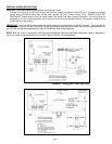
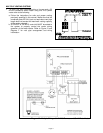
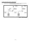
Diagram B – Internal Wiring Schematic for PVU-300