


Page 5
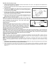
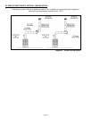
SIDE WALL VENT HOOD INSTALLATION
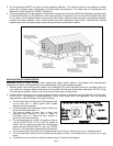
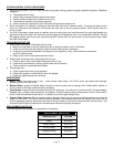
1. Use the inside wall plate as a template to mark the hole location. Cut a hole 1 inch larger than the marked hole to
facilitate easy installation (See Figure 4)
2. Center vent hood through the hole from outside. Fasten the vent hood to the outside wall with the appropriate type of
mounting screws.
3. Fasten the wall end plate to the inside wall with the appropriate type of
mounting screws. NOTE: Apply sealant to the outside mounting plate of
the vent hood to prevent leakage.
4. Connect the venter outlet or a properly sized section of vent pipe onto
the inner pipe of the vent hood. Fasten the connection with three sheet
metal screws or equivalent fastening method.
5. Seal the vent hood inlet connection and any other vent pipe joints on the
outlet side of the venter with an approved high temperature silicone
adhesive sealant or equivalent material.
NOTE: Do not enclose the space between the plates on the outside of the
vent hood or between the inner and outer pipe of the vent hood. This might
cause overheating of the wall structure. Local codes might require
fencing around the vent hood outlet.
V
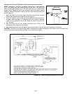
ENTER LOCATION
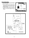
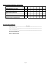
Install the power venter onto the vent hood inlet or as close to the vent
hood inlet as possible. Always install the venter such that the motor
shaft is horizontal and the pressure switch diaphragm is vertical (See
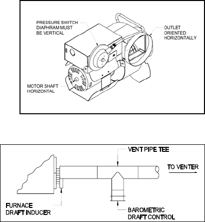
Figure 5) When venting a draft induced gas fired heating appliance a
barometric draft control must be installed on the vent system between
the appliance outlet and the venter inlet. (See Figure 6)
CAUTION: The power venter should never be installed with the motor shaft in the vertical position. This could allow heat
to be trapped in the venter housing and radiate through the motor possibly causing motor deterioration and premature
failure. Never attach the venter inlet directly to the outlet of the heating appliance. Also, a minimum of 6 inches clearance
between the venter housing and combustible materials must be maintained.
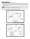
C
ONNECTING VENTER TO THE FLUE PIPE
NOTE: The power venter should be supported in accordance with National Fuel Gas Code Z223.1, Section 7.910 as
follows; A vent connector shall be supported for the design and weight of the material employed to maintain clearances
and to prevent physical damage and separation of joints.
NOTE: For gas fired heating appliances not equipped with a draft hood, a barometric draft control must be installed
between the heating appliance exhaust outlet and the power venter inlet to regulate any draft fluctuations during
operation.
1. Use approved vent connectors to join the heating appliance outlet to the venter inlet securing each joint with sheet
metal screws or equivalent means of fastening when required.
2. Seal all pipe joints on the outlet side of the venter with a high temperature silicone adhesive or equivalent. Test the
vent connections for leaks by using a soap solution as recommended by the National Fuel Gas Code, A.N.S.I. Z223.1,
Section 4.1.1.
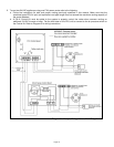
Figure 5
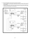
Figure 6