


5
Before you install the appliance, please make sure that
the local distribution conditions (nature of gas and pressure) and the adjustment of the
appliance are compatible. For adjustment conditions for this appliance, see ‘Connecting the
cooktop to the gas supply’ and ‘Gas rate summary’.
a suitable isolating switch is incorporated in the fixed wiring in an acceptable position.
the appliance is connected to a power outlet that is electrically grounded in accordance with
local codes or in the absence of local codes, with the National Electric Code ANSI/NFPA 70 or CSA
C22.2 (Canada).
there is a power outlet (120V 60Hz) within reach of the appliance cable (for CG122 models, a
grounded power outlet should be located within 36”/914 mm of the right rear corner of the
cutout; for CG244 models, a grounded power outlet should be located within 36”/914 mm of the
center rear side of the cutout). This must be accessible after installation. The mains power supply
cable should not touch any metal parts.
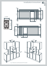
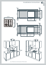
the countertop is square and level and no structural members interfere with space requirements.
the countertop is made of heat-resistant material.
the gas shut-off valve is accessible after installation.
When you install the appliance
Gas supply connection
This appliance is factory set for use with Natural Gas at 4” of water column pressure. It can also
be used on LP/Propane Gas at 11” of water column pressure after conversion. Manifold pressure
should be checked with a manometer.
Incoming line pressure upstream from the gas pressure regulator must be 1” W.C.P higher than
the manifold pressure in order to check the regulator.
The gas pressure regulator supplied with this cooktop can withstand a maximum input pressure
of ½ p.s.i. (14” W.C.P). If the line pressure is in excess of that amount, a step-down regulator will
be required.
A manual shut-off valve must be installed in an accessible location in the gas line external to the
appliance for the purpose of turning on or shutting off gas to the appliance. (In Massachusetts,
such shut-off devices should be approved by the Board of State Examiners of Plumbers & Gas
Fitters).
Gas connection to the product must use the components supplied, see ‘Installing the gas
pressure regulator’ and ‘Gas connection specifications’.
Ensure the washers (supplied) are correctly positioned, see ‘Installing the gas pressure regulator’
and ‘Gas connection specifications’. Failure to do so will cause a gas leak.
Leak testing
Leak testing of the appliance shall be conducted according to the manufacturer’s instructions.
The appliance, its individual shutoff valve and the gas pressure regulator must be disconnected
from the gas supply piping system during any pressure testing of that system in excess of ½ p.s.i
(3.5 kPa).
The appliance must be isolated from the gas supply piping system by closing its individual
shutoff valve during any pressure testing of the gas supply piping system at test pressures at or
less than ½ p.s.i. (3.5 kPa).
Minimum gas supply pressure for regulator testing 5” W.C. Natural Gas, 12” LP Gas.
After installing the gas supply or converting to a different gas type and making all connections,
check thoroughly for possible leaks.
Safety and warnings
US CA