


INSTALLATION INSTRUCTIONS
5
US
1 Turn off the main electrical supply.
2 Ensure all gas valves are turned off.
3 Remove all trivets and burner heads.
4 Pull off knobs.
5 Remove the 2 screws holding each burner
(3 on the wok burner).
6 Partially lift the hob and unplug the electrode on the mini-
auxiliary burner to allow hob removal. Beware of sharp edges.
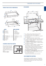
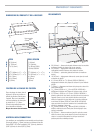
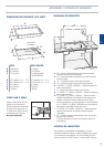
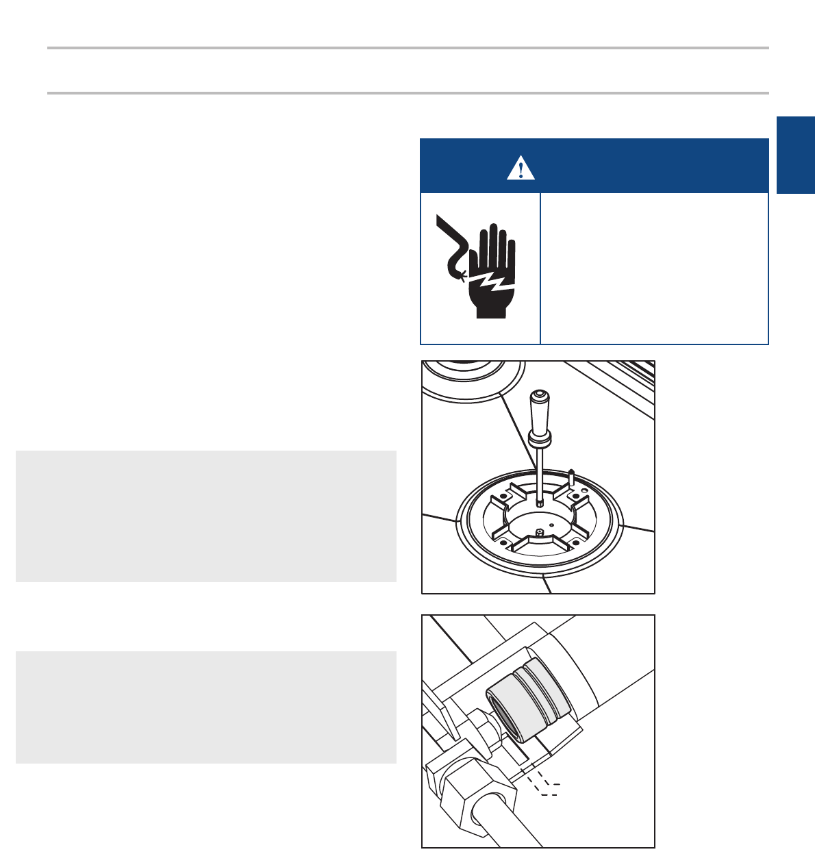
7 Unscrew the orifices and replace them with the correct ones.
(size numbers are stamped on the side, eg. 70= 0.70mm)
(see figure 1).
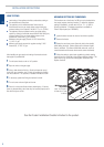
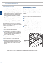
8 Reset the venturi position aligning the end of the venturi tube
with the edge of the slot in the bracket below it. Outermost
position for LPG, innermost for NG (see figure 2). Some fine
adjustment may be required for local conditions.
9 To replace the CG901M hob, repeat steps 3-6 in reverse.
10 Reset the minimum setting. See ‘Minimum Setting’ overleaf.
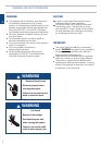
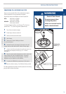
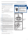
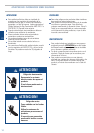
WARNING
Electrical Shock Hazard
Disconnect power before
servicing the product.
Failure to do so could result in
death or electrical shock.
Changing the
Orifice figure 1
The label supplied with the orifices should be placed over the existing
gas type label to indicate the change.
Venturi Position
figure 2
CG901M onlyCG901M only
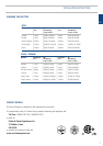
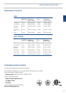
CONVERSION TO A DIFFERENT GAS TYPE
Burners can be used with NG or LPG, provided that the injector
orifices appropriate for the gas delivered are installed.
High altitude orifices are available from Fisher & Paykel USA.
GC36 NG Kit Part No. 530463
LP Kit Part No. 530464
GC901/M NG Kit Part No. 531566
LP Kit Part No. 531567
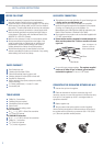
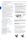
To change the injector orifices, you will need a
9
/
32
" (7mm) box
spanner and a
13
/
32
" (10mm) ring spanner (CG901M only).
NG Venturi Position
LPG Venturi Position