


INSTALLATION INSTRUCTIONS
6
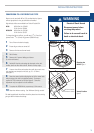
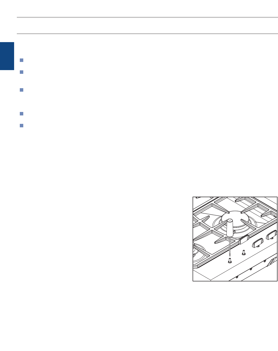
MINIMUM SETTING OR TURNDOWN
This has been set at the factory for NG but can be checked after
the correct pressure has been reached. To adjust for minimum
setting (if applicable), you will need a Ø
7
/
64
" x 1
3
/
4
" (Ø2.5 x
45mm) screwdriver. (A suitable screwdriver is available as
Fisher & Paykel spare part. FB200467).
1 Ignite the burner and set the knob to its minimum position.
2 Remove the knobs.
3 Rotate the turn down screw (down the hole in the spindle)
while holding the shaft. Rotate slowly until a minimum regular
flame is achieved. (The flame will diminish when the screw is
turned clockwise and increase when turned counter clockwise).
4 When the setting is right check regulation by quickly rotating
the knob from the maximum to the minimum delivery position. The
flame must not go out and the autoreignition should not click.
Replace the knob.
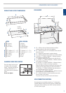
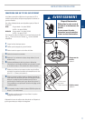
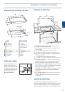
US
Minimum setting
adjustment
(Note: this diagram is
of GC901 but is similar
for GC36).
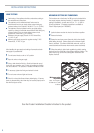
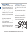
After installing the gas supply and making all connections check
thoroughly for possible leaks.
1 Turn all control knobs on unit to "off" position.
2 Open the valve on the gas supply.
3 Using a leak detection fluid (e.g. Rocol leak detection spray)
check each gas connection one at a time by brushing the solution
over the connection. The presence of bubbles will indicate a leak.
4 If necessary, tighten the fitting and recheck for leaks.
5 Turn on burner valve and light each burner.
6 Check for a clear blue flame without yellow tipping. If burners
show any abnormalities, check that they are located properly and in
line with the injector orifice.
LEAK TESTING
Leak testing of the appliance shall be conducted according to
the manufacturer's instructions.
The appliance and it's individual shutoff valve must be
disconnected from the gas supply piping system during any
pressure testing of that system in excess of
1
/
2
p.s.i. (3.5kPa).
The appliance must be isolated from the gas supply piping
system by closing it's individual manual shutoff valve during any
pressure testing of the gas supply piping system at test
pressures at or less than
1
/
2
p.s.i.(3.5kPa).
Maximum inlet gas supply pressure 4" W.C. Natural Gas,
11" W.C. LP gas.
Minimum gas supply pressure for regulator testing 5" W.C.
Natural Gas, 12" W.C. LP gas.
See the Product Installation Checklist attached to the product.