


15
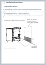
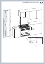
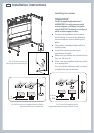
Installation instructions
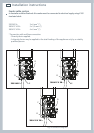
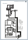
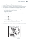
Wiring diagram
ELECTRIC DIAGRAM KEY
F1 Oven switch
ST Safety thermostat
TL Thermal overload
TL1 Induction hob thermal overload
PR Electronic programmer
PB Temperature probe
TS Oven temperature selector
EC Oven function selector (encoder)
R1 Relay 1
R2 Relay 2
LF Oven lamp
TR Oven lamps transformer
S1 Thermostat pilot lamp
S2 Line pilot lamp
C Oven top heating element
G Oven grill heating element
S Oven bottom heating element
CI Oven circular heating element
IU-LH Induction unit, left zones
IU-RH Induction unit, right zones
UD Induction units user display
PCB Induction units PCB
RSI Rotary selector interface
GIR Rotisserie motor
V Oven fan motor
CF Cooling fan motor
M Terminal block
T Earth connection
R1
R2
PT1
PT2
P8
P9
3a
3
4a
4
5a
5
6a
6
7a
7
GSCI C
8a
8
9a
9
10a
10
11a
11
1a
1
2a
2
LF
V
GIR
LF
TR
ST
12a
12
X1
TL TL1
PR
PR
PR
TS
EC
P4
PB
X0
F1
F1
IU-LH
IU-RH
RSI RSI RSI RSI
UD
PCB
CF
S1
S2
42
135
M
T
N
L1
N
L1
X6/X18/X19
X6/X18/X19
X1
X2
X8