20
Technical Data
RBC20-60
RBC20-60R
Nominal Chilling Capacity 60Kg
60Kg
Duty @ -15°C 3800w
3800w
Fans 3
3
Evaporating Temperature -15°C
-15°C
HP Switch Setting
Refrigerant Control TEV
TEV
Refrigerant R404a
R404a
Refrigerant Quantity
System 1 1900grms
System 2 1900grms
Electrical Supply 400/3/50 – 16amp
230/1/50 13 amp (Fans & Defrost)
Total Heat Rejection 1500w
Important Note
There are two refrigeration systems on this model
Refrigerant used is R404A.
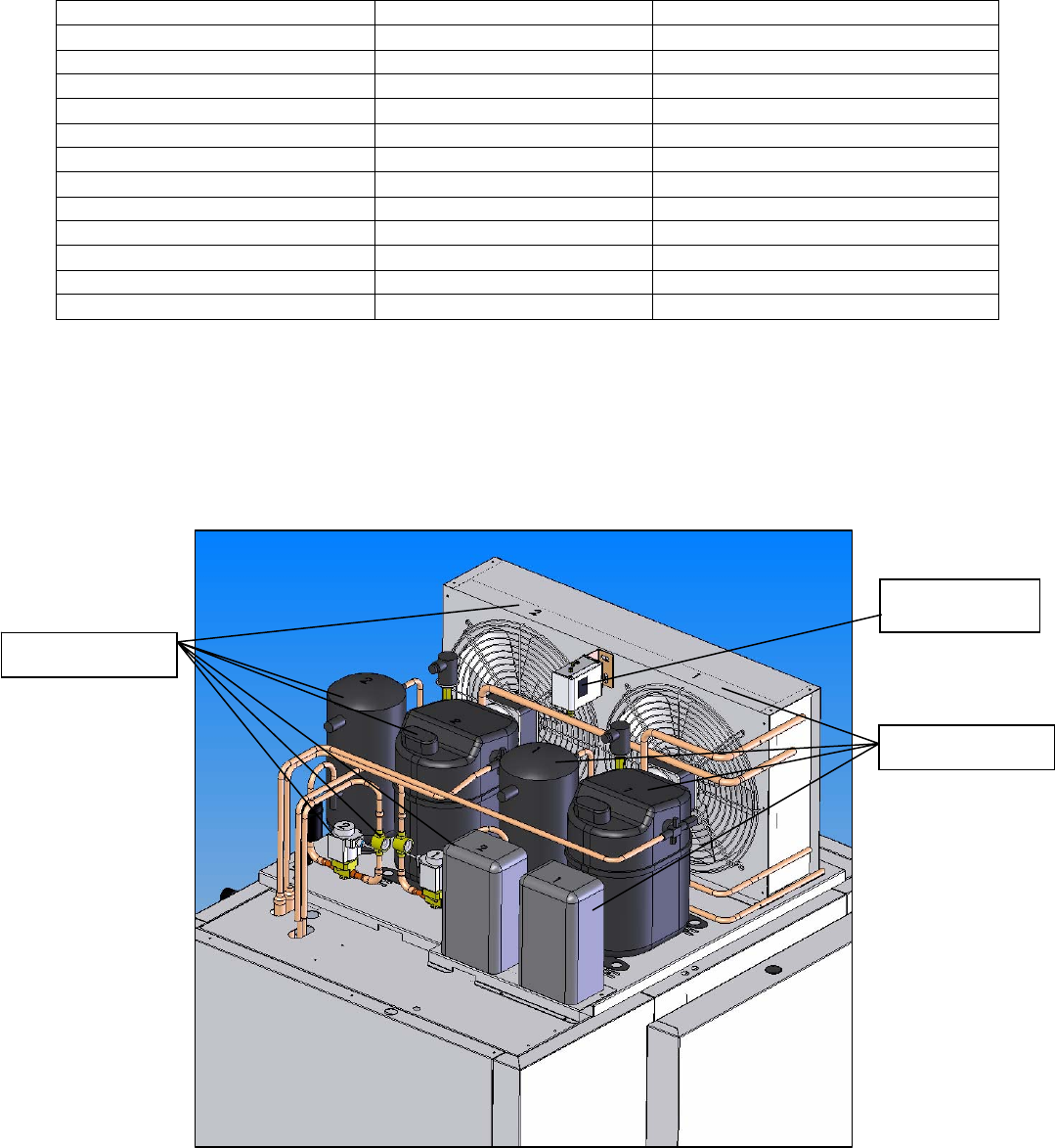
The RBC20-60 has two separate refrigeration systems comprising, two condensing units, a twin circuit condenser (see
below) and a twin circuit evaporator. (See page 21for assembly details and page 22 for schematic dual circuit refrigeration
layout).
The condenser fan on system 2 is controlled by the HP switch, which is set at 18 BAR with a 3 BAR diff.
The RBC20-60R has the same refrigeration systems but the condensing units are remotely sited.
The parameter ‘Capacity Enable’ is set to ‘AUTO’ to allow for both condensing units to be running at the start of the chill
cycle therefore maximising the heat extraction from the product. On reaching ‘HOLD’ one of the condensing units will shut
down. During the ‘HOLD’ mode one compressor will control the temperature throughout unless the temperature exceeds
the capacity control limit.
Refrigerant control is by expansion valve to control the correct amount of refrigerant required to meet the demand of the
evaporator. (See page 21 for assembly detail).
Expansion Valve Setting (Superheat)
Adjust the superheat by turning the expansion valve setting spindle anti clockwise until back seated then turn the setting
spindle clockwise THREE FULL TURNS IN.
CONDENSING UNIT ASSEMBLY RBC20-60
System 2
System 1
HP Switch


