


1-1
PERFORMANCE PRO SERIES GAS FRYERS MODELS 35 & 45
CHAPTER 1: SERVICE PROCEDURES
1.1 General
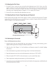
Performance Pro Series gas fryers (formerly Master Jet 35- and 45-series fryers) contain a welded
stainless steel frypot directly heated by gas fl ames diffused evenly over its lower surface by ceramic
targets. The fl ames originate from orifi ces in a U-shaped burner manifold positioned beneath the frypot.
They are equipped with either a millivolt gas valve or electromechanical gas valve that regulates gas fl ow
to the manifold. For operating information, refer to the Performance Pro Series Gas Fryers Models 35 &
45 Installation and Operation manual (P/N 819-6042). (Furthermore, referred to as the Installation and
Operation manual.)
1.1.1 Pilot Ignition
The pilot system is the pilot orifi ce, pilot hood, and thermopile. The pilot serves two purposes: lighting
the burners and heating the thermopile. In operation, the thermopile is in contact with the pilot fl ame
and generates millivolts. The millivolt output passes through a normally closed high-limit switch and
energizes the gas valve pilot coil, which opens the pilot valve. If the pilot fl ame is extinguished, the gas
valve pilot coil loses voltage and the pilot valve closes.
In units equipped with 24-volt electromechanical gas valves, a separate 24-volt circuit activated by the
fryer power switch provides voltage through the thermostat or controller to the gas valve main coil,
which opens the main valve. The main gas valve will not open if the pilot valve is not open. Light the
pilot fl ame manually using a match or the optional built-in piezo ignitor after installing the fryer.
1.1.2 Electronic Ignition
In units confi gured for electronic ignition, a black ignition module connected to an ignitor assembly
replaces the pilot system. The ignition module performs three important functions: supply voltage to the
gas valve, provide an ignition spark, and proof the pilot fl ame. The module contains a 4.5-second time
delay circuit and a coil that activates the gas valve. The ignitor assembly consists of a spark plug, a pilot,
and a fl ame sensor element.
At start-up the power switch is placed in the ON position, supplying 12 VDC to the heat control circuitry
in the controller or computer and to one side of the heat relay coil on the interface board. If resistance in
the temperature probe indicates the temperature in the frypot is below 180°F (82°C), the current fl ows
through a melt cycle circuit where a timer switch alternately closes for 3 seconds and opens for 24
seconds. If the temperature is 180°F (82°C) or above, the current fl ows through a heat circuit, bypassing
the timer switch. In either case, current is supplied to the other leg of the heat relay coil, which closes an
electronic switch in the 24 VAC circuit to provide current to the ignition module.
Circuitry in the ignition module sends 24 VAC current to the gas valve via a normally closed high-limit
switch and a drain safety switch. Simultaneously, the module causes the ignitor to spark for 4 seconds
to light the pilot fl ame. A fl ame sensor verifi es that the pilot is lit by measuring the fl ow of microamps
through the fl ame (can vary, averages 1.9 microamps). If the pilot does not light or is extinguished,
current to the ignition module is stopped, preventing the main valve from opening, and the ignition
module locks out until the power switch is turned OFF, then back ON.