


7-2
4. Dismount the component to be replaced and install the new component, being sure that any
required spacers, insulation, washers, etc. are in place.
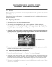
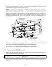
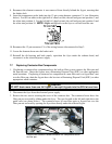
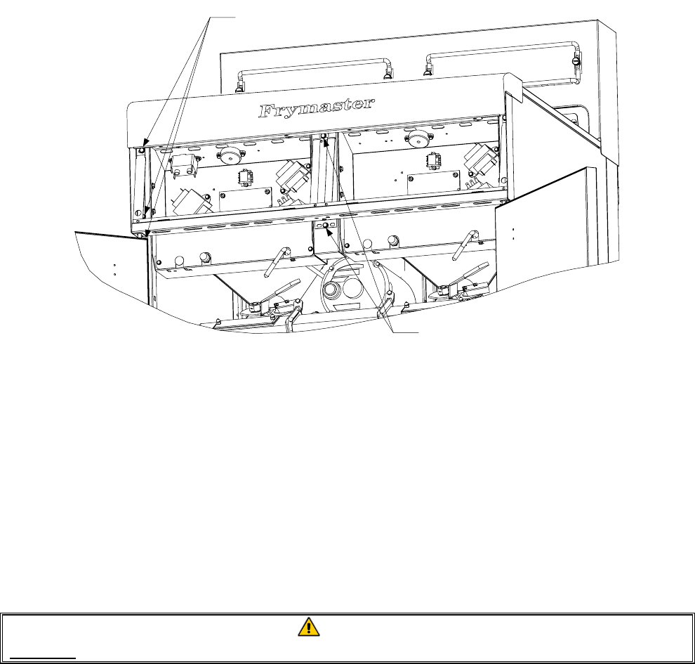
NOTE: If more room to work is required, the control panel frame assembly may be removed by
removing the hex head screws that secure it to the fryer cabinet (see illustration below). If this
option is chosen, all front panel assemblies must be removed per steps 2-4 above. The cover
plate on the lower front of the component box may also be removed if desired. Removing the
component box itself from the fryer is not recommended due to the difficulty involved in
disconnecting and reconnecting the oil-return valve rods, which pass through openings in the
component box.
Remove these three
screws at each end.
Remove these two screws
from the center supports.
Removing the Control Panel Frame and Top Cap Assembly
5. Reconnect the wiring disconnected in Steps 2 and 3, referring to your notes and the wiring
diagrams on the fryer door to ensure that the connections are properly made. Also, verify that no
other wiring was disconnected accidentally during the replacement process.
6. Reverse steps 1-4 to complete the replacement and return the fryer to service.
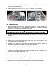
7.4 Replacing a High-Limit Thermostat
1. Remove the filter pan and lid from the unit. Drain the frypots into a Shortening Disposal Unit
(SDU) or other appropriate metal container.
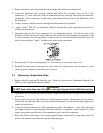
DANGER
DO NOT drain more than one full frypot or two split frypots into the SDU at one time.
2. Disconnect the fryer from the electrical power supply and reposition it to gain access to the rear
of the fryer.