


7-3
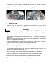
3. Remove the four screws from both the left and right sides of the lower back panel.
4. Locate the high-limit that is being replaced and follow the two-black wires to the 12-pin
connector C-6. Note where the leads are connected prior to removing them from the connector.
Unplug the 12-pin connector C-6 and using a pin-pusher push the pins of the high-limit out of
the connector.
5. Using a wrench, carefully unscrew the high-limit thermostat to be replaced.
6. Apply Loctite
™
PST 567 or equivalent sealant to the threads of the replacement and screw it
securely into the frypot.
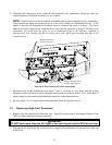
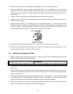
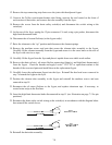
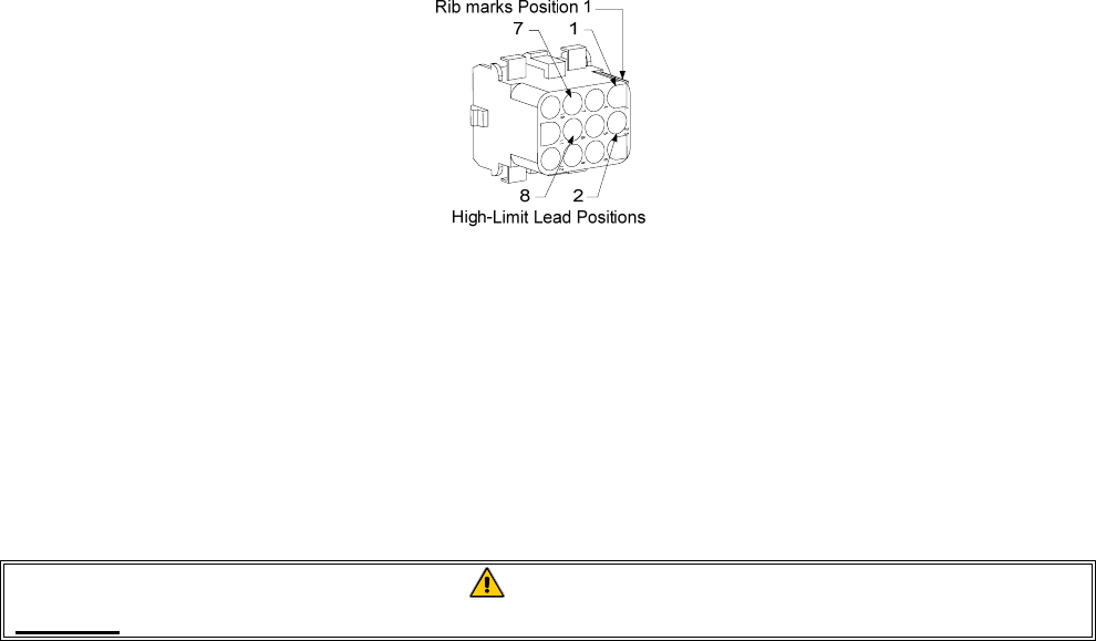
7. Insert the leads into the 12-pin connector C-6 (see illustration below). For full-vat units or the
left half of a dual-vat unit (as viewed from the rear of the fryer) the leads go into positions 1 and
2 of the connector. For the right half of a dual-vat unit (as viewed from the rear of the fryer), the
leads go into positions 7 and 8. In either case, polarity does not matter.
8. Reconnect the 12-pin connecting plug C-6. Use wire ties to secure any loose wires.
9. Reinstall the back panels reposition the fryer under the exhaust hood, and reconnect it to the
electrical power supply to return the fryer to service.
7.5 Replacing a Temperature Probe
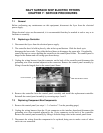
1. Remove the filter pan and lid from the unit. Drain the frypots into a Shortening Disposal Unit
(SDU) or other appropriate metal container.
DANGER
DO NOT drain more than one full frypot or two split frypots into the SDU at one time.
2. Disconnect the fryer from the electrical power supply and reposition it to gain access to the rear
of the fryer.
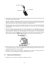
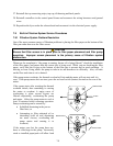
3. Remove the four screws from both sides of the lower back panel. Then remove the two screws
on both the left and right sides of the back of the tilt housing. Lift the tilt housing straight up to
remove from the fryer.
4. Locate the red and white wires of the temperature probe to be replaced. Note where the leads
are connected prior to removing them from the connector. Unplug the 12-pin connector C-6 and
using a pin-pusher push the pins of the temperature probe out of the connector.
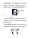
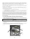
5. Raise the element and remove the securing probe bracket and metal tie wraps that secure the
probe to the element (see illustration on the following page).