


Cabinet Service Procedures
2-7
• ERR LED toggles when a communication error is detected; it’s not unusual to see a flash,
but regular flashing means communications problems.
• LED5 and LED6 used for programming/debugging; have no diagnostic function.
• LED7 When lit, the master control is executing a time or temp query operation on the front
side.
• LED8 When lit, the master control is executing a time or temp query operation on the back
side.
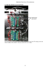
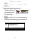
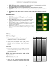
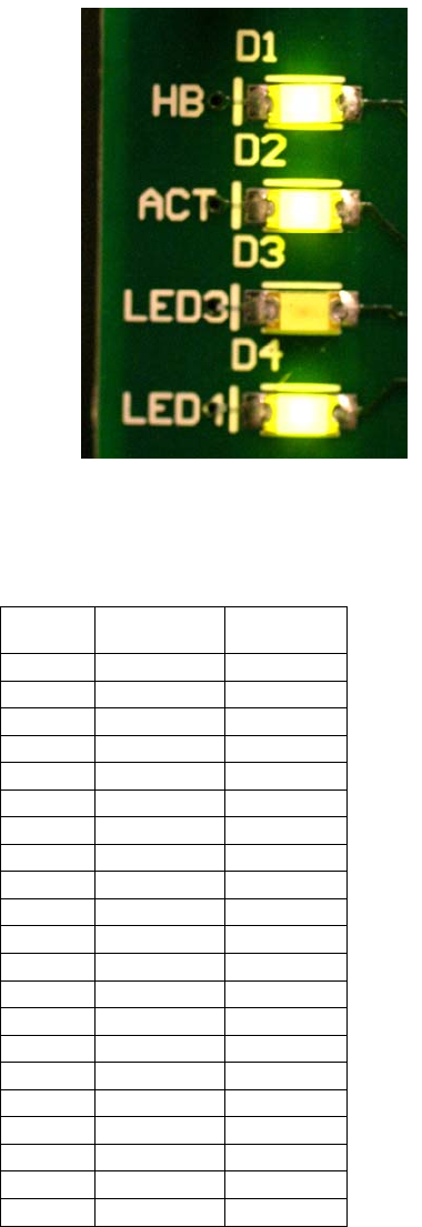
Distribution Board
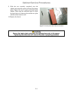
• HB LED is a heartbeat LED; toggles on / off to indicate
processor is running.
• ACT LED flashes when it receives a valid communication
packet; it should be flashing every few seconds or faster.
• LED3 Toggles if there is a communications error on a packet
directed to the distribution board. Can flash on occasion;
shouldn’t flash regularly.
• LED1 flashes if there is voltage being applied to one or more
heaters on that distribution board; one or more plate is calling
for heat.
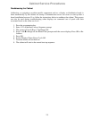
2.5 Tests
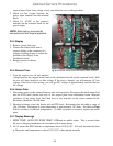
2.5.1 Power Supply
1. Disconnect power and check all terminals and
connections for loose or disconnected wires.
2. Apply power and check for 5VDC at the power-in
terminal on the distribution board and chassis
ground.
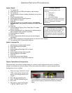
2.5.2 RTD
1. Remove the leads from the suspect RTD and test for
resistance. Selected temperatures and resistances are
show in chart at right.
NOTE: After testing, reconnect all leads to their
original positions.
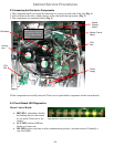
2.5.3 Distribution Boards
1. Check for line voltage between the heater plate
terminal on the board and the terminal block for the
Sensor
(°F)
Resistance
Sensor
(°C)
60 106.065 15.55
70 108.224 21.11
80 110.380 26.66
90 112.532 32.22
100 114.680 37.77
110 116.825 43.33
120 118.966 48.88
130 121.104 54.44
140 123.239 60.00
150 125.369 65.55
160 127.496 71.11
170 129.620 76.66
180 131.740 82.22
190 133.856 87.77
200 135.969 93.33
210 138.078 98.88
220 140.184 104.44
230 142.286 110.00
240 144.385 115.55
250 146.480 121.11
260 148.570 126.66
RTD resistance chart
Fig.5:DistributionBoardLED's