


7-8
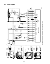
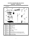
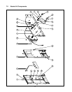
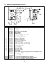
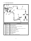
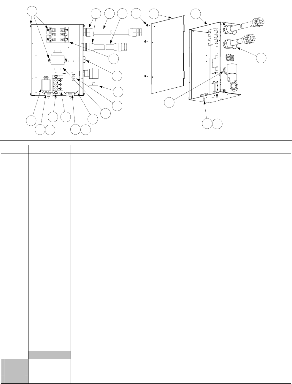
7.5 Electrical Components and Controllers
1
2
3
4
2
3
6
8
9
10
11
12
13 14 15
12
16 17
18
20
21
19
5
7
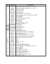
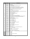
ITEM PART # COMPONENT
1 807-1396 Relay, 24VDC
2 807-1308 Holder, Fuse
3 807-1555 Fuse, 5 Amp
4 809-0362 Screw, #8 x 1¼-inch Hex Head
5 807-0878 Block, Terminal
6 807-0263 Terminal, Split
7 807-0680 Transformer, 208/240VAC – 24VAC
8 807-0070 Terminal, Ground Lug
9 806-4770 Valve Assembly, Solenoid
10 807-0875 Connector, 15-pin Female
11 810-1202 Contactor, 40 Amp 3 Pole
12 809-0361 Screw, #8 x ½-inch Hex Head
13 807-1292 Fitting, Plastic Conduit
14 812-0994 Conduit, ½-inch Plastic (17 inches long)
15 812-0992 Conduit, ½-inch Plastic (15 inches long)
16 900-7853 Cover, Component Box
17 823-1820 Box, Component
18 810-0044 Button, ⅞-inch Plug
19 809-0454 Nut, ½-inch Conduit
20 809-0096 Screw, 6-32 x ⅝-inch
21 809-0250 Nut, 6-32 Keps
* 806-5332 Cordset, Basket Lift (used with 480/120VAC dual-voltage units only)
* WIR0013SP Wire Assembly, 8SMS Contactor Box
* 806-4702 Cable, 8SMS Controller
* Controller, 8SMS
106-0371 CE and non-CE with AutoFill and AutoSkim
106-0373 CE and Non-CE with AutoFill but without AutoSkim
106-0374 CE and Non-CE without Autofill or Autoskim
* Not illustrated.