1-7
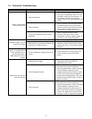
1.4 Technician Troubleshooting
PROBLEM PROBABLE CAUSES CORRECTIVE ACTION
A. Failed transformer.
A. Check for line voltage on the primary
(line) side of transformer and 12VAC on
secondary (load) side of transformer. If
line voltage is present but secondary
voltage is not 12VAC, the transformer has
failed.
B. Failed computer.
B. Check continuity between right terminal
of secondary (load) side of transformer
and Pin 9 of the 9-pin connector when the
cover interlock switch is closed. If
resistance is zero, replace the computer.
Display remains blank
when unit turned on.
C. Failed cover interlock switch or failed
high limit.
C. Check continuity between switch
terminals when the switch is closed.
If resistance is infinite, replace switch. If
resistance is zero, replace high limit.
A. Failed motor. A. If platen is heating, replace motor.
Computer display is on, but
motor is not running
B. Broken/loose wire between computer and
latch relay or failed latch relay.
B. Check for 12VDC on Pins 6 & 7 of
computer. If present and wiring is intact,
replace latch relay. If not present, replace
computer.
Motor is running at wrong
speed (i.e. average time for
three individual buns to
pass through toaster is
NOT between 15 and 18
seconds).
A. Toaster improperly configured for power
supply.
A. Check data plate for voltage rating, and
verify that power supply and toaster
match.
A. Improper power-supply.
A. Verify that the power supply is 20 amp
single-phase 200, 208 or 240VAC
(depending upon model).
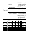
B. Failed temperature probe.
B. Use a temperature-measuring device to
determine actual platen temperature. If
measured temperature is within 10 degrees
of the temperature displayed on the
computer and the probe resistance at pins
3 and 5 of the 9-pin connector does not
correspond to the appropriate value in the
probe resistance chart on Pages 24 and 25,
replace the probe.
Platen heats, but unit does
not reach setpoint.
C. Failed computer.
C. Use a temperature-measuring device to
determine actual platen temperature. If
measured temperature is within 10 degrees
of the temperature displayed on the
computer and probe resistance at pins 3
and 5 of the 9-pin connector corresponds
to the value in the probe resistance chart
on Pages 24 and 25, replace the computer.


