


1-7
7. Place the fryer power switch (and the gas valve in non-CE fryers) in the OFF position. Remove
the fitting from the pressure tap hole and reinstall the pressure tap plug.
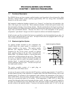
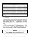
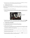
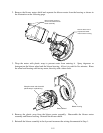
1.5 Measuring Flame Current
When the burner flame is properly adjusted, it will produce a current between 2.5 μA and 3.5 μA.
Flame current is measured by placing a microamp (not milliamp) meter in series with the sensing
wire on the ignitor.
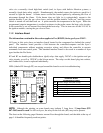
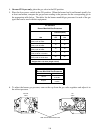
1. Place the fryer power switch in the OFF position.
2. Disconnect the sensing wire from one of the burner ignitors and connect it to the positive lead of
the meter. Connect the negative lead of the meter to the terminal from which the sensing wire
was removed.
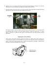
3. Place the fryer power switch in the ON position to light the burners. After the frypot
temperature reaches 200°F (93°C), wait at least one minute before checking the reading. NOTE:
The closer the unit is to normal operating temperature, the more accurate the reading will be.
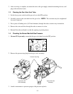
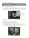
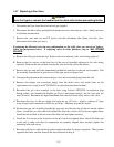
1.6 Replacing Fryer Components
1.6.1 Replacing the Controller or the Controller Wiring Harness
1. Unplug all electrical power cords.
2. Lift up on the bezel to disengage the tabs on its lower edge from the control panel frame. Slide
the bezel down to disengage the upper tabs. Remove the top two screws. Swing the controller
out from the top and allow it to rest on its hinge tabs.
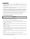
3. Disconnect the wiring harness from the back of the controller and, if replacing the harness,
disconnect it from the interface board.
4. Disconnect the ground wire from the controller. Remove the controller by lifting it from the
hinge slots in the control panel frame.
5. Reverse the procedure to install a new controller or wiring harness. NOTE: Ensure that the
ferrite bead (black ring) in the harness is at the controller end.
Flame Sensor Wire
(
Ri
g
ht Burner
)