


1-9
b. If replacing the high-limit thermostat, use a pin pusher to disconnect the lead running to the
connector and insert the corresponding lead from the new thermostat. Disconnect the other
lead from the drain safety switch and connect the remaining lead from the new thermostat.
17. Reverse steps 1-12 to reassemble the fryer.
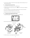
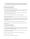
1.6.3 Replacing the Interface Board
1. Disconnect the fryer from the electrical power supply.
2. Lift up on the bezel to disengage the tabs on its lower edge from the control panel frame. Slide
the bezel down to disengage the upper tabs. Remove the top two screws. Swing the controller out
from the top and allow it to rest on its hinge tabs.
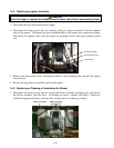
3. Disconnect the wiring harness from the back of the controller and from the interface board, and
disconnect the ground wire from the controller.
4. Remove the controller by lifting it from the hinge slots in the control panel frame.
5. Disconnect the wires attached to the interface board, marking or making a note of the wires and
terminals to facilitate reconnection.
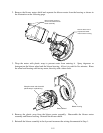
6. Remove the nuts at each corner of the interface board and carefully pull it from the studs far
enough to allow the connector on the back of the board to be disconnected, then remove the
board from the box. When removing the board, be careful not to lose the spacers that fit over the
studs behind the board.
7. Recover the relay(s) from the failed interface board and install on the replacement board.
8. Reverse the procedure to install the replacement board, being sure that the spacers behind the
board are in place.
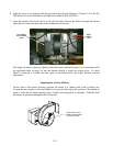
1.6.4 Replacing an Ignition Module
1. Disconnect the fryer from the electrical supply.
2. Lift up on the bezel to disengage the tabs on its lower edge from the control panel frame. Slide
the bezel down to disengage the upper tabs. Remove the top two screws. Swing the controller out
from the top and allow it to rest on its hinge tabs.
3. Disconnect the wires from the ignition module, marking or making a note of the wires and
terminals to facilitate reconnection.
4. Remove the four ignition module screws and pull the module from the component box.
5. Move the spacers to the new module.
6. Reverse the procedure to install the replacement module.