


1-31
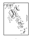
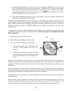
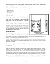
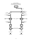
100/120V Modular Basket Lift Assembly
P/N 1061807SP (TYPICAL)
the frypot until the rod loses contact with the upper microswitch, cutting power to the motor and
again reversing the direction of current flow.
Problems with the basket lift can be grouped into three categories:
• Binds and jams
• Motors and gears
• Electronics.
BINDS AND JAMS
Noisy, jerky or erratic movement of the lifts is usually
due to lack of lubrication of the rods and bushings.
Apply a light coat of Lubriplate
®
or similar lightweight
white grease to the rod and bushings to correct the
problem.
Another possible cause of binding is improper
positioning of the motor, which prevents the gear from
correctly engaging the teeth in the rod. To correct the
problem, loosen the screws that hold the motor in place
and move it forward or backward until the rod has just
enough slack to be rotated slightly.
MOTORS AND GEARS
The most likely problem to be encountered in this
category is erratic motion of the lift due to a worn drive
gear. Failure to keep the lift rod and bushings properly lubricated will cause unnecessary wear of
the gear. Correct the problem by replacing the worn gear.
If the lift cycles correctly but fails to remain in the up position (i.e., goes up, but then slowly settles
back down into the frypot), the problem is a failed motor brake. This cannot be repaired and the
motor must be replaced.
If power is reaching the motor but the motor fails to run, it is burned out and must be replaced.
ELECTRONICS
Within this category are problems associated with the relays, microswitches, capacitors, resistors,
interface board, wiring, and controls. The most common problem in this category is a lift that
continuously travels up and down. This is usually caused by a microswitch that is out of adjustment.
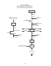
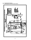
Troubleshooting the electronics of the basket lift is the process of verifying current flow through the
individual components up to and including the motor. Using a multimeter set to the 250 VAC range,
check the connections on both sides of the component for the presence of the applied line voltage.
The wiring diagram on the Page 1-38 identifies the components and wiring connection points.