


Frymaster L.L.C., 8700 Line Avenue 71106, P.O. Box 51000, Shreveport, Louisiana 71135-1000
318-865-1711 FAX 318-862-2394
Printed in the United States Service Hotline
Page
16
1-800-24-FRYER
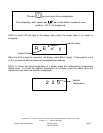
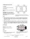
Output power
• With the computer plugged in and turned on, check for 14VDC from pin 5 on the computer
terminal to ground.
10.3 Transformer
Symptom: Unit has no display
Test:
• Line voltage should be measured across the
input side of the transformer; 12VAC should be
measured across the output side.
10.4 Plate Heater RTD
The following tests are conducted without power
applied.
Symptom: Unit displays Probe. Actual plate temp is
not within 5°F of setpoint. Temperature must be
taken from thermocouple built into unit.
Test:
• With power removed from the HLZ, measure
resistance between pins 9 and 13 on the
computer plug and compare readings to listing on
the resistance chart. With the unit cool, the
resistance reading should approximate the
resistance shown on the chart for the room temperature. Also check for short to ground. A
chaffed wire shorting to the chassis can produce resistance readings within proper range.
10.5 Air RTD
Symptom: Unit displays Probe. Actual air temp is not within 5°F of setpoint.
Test:
• With power removed from the HLZ, measure resistance between pins 14 and 15 on the
computer plug and compare with air temperature on the resistance chart in this section.
Also check for short to ground. A chaffed wire shorting to the chassis can produce
resistance readings within proper range.
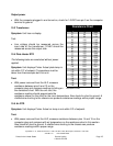
Centegrade Fahrenheit Ohms
21 70 1080
27 80 1101
32 90 1122
38 100 1143
43 110 1164
49 120 1185
54 130 1206
60 140 1226
66 150 1247
71 160 1268
77 170 1289
82 180 1309
88 190 1330
93 200 1350
99 210 1371
104 220 1391
110 230 1412
116 240 1432
121 250 1453
127 260 1473
132 270 1493
138 280 1514
143 290 1534
149 300 1554
Resistance chart
Resistance Chart