


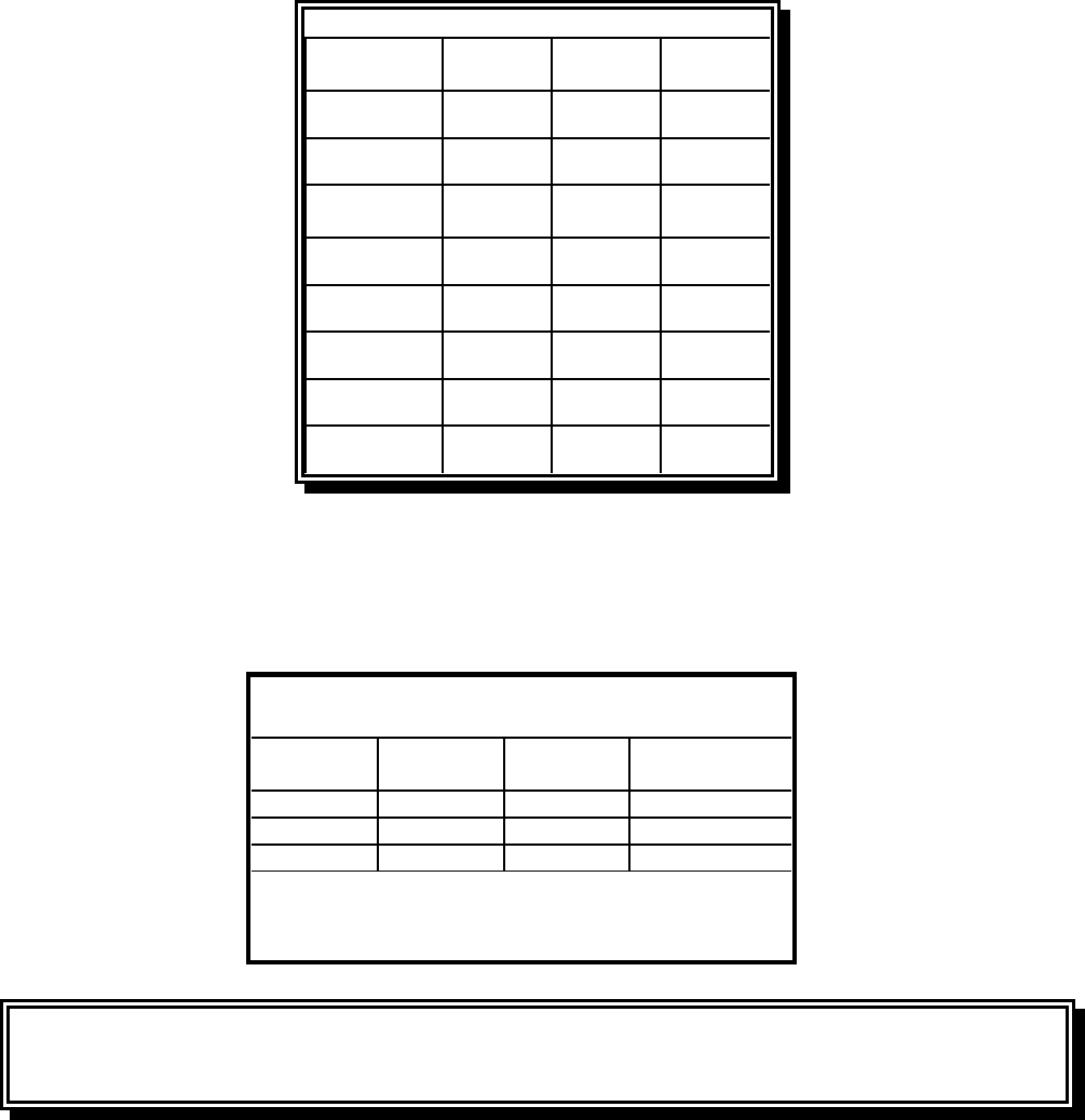
2-6
BE
I2E+(S)
I3P
G20/G25
G31
20/25
37
DE
I2 ELL
13P
G20/G25
G31
20
50
FR
II2Esi3P
G20/G25
G31
20/25
37 ET 50
LU
I2E G20/G25 20/25
ES
II2H3P
G20
G31
20
37 ET 50
NL
II2L3P
G25
G31
25
50
IE-PT-GB
II2H3P
G20
G31
20
37
DK-GR-IT
I2 H G20 20
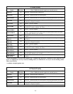
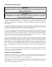
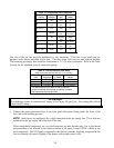
Table 3: CE Approved Gas Categories
Country Category Gas
Pressure
(mbar)
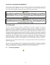
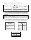
The size of the gas line used for installation is very important. If the line is too small, the gas
pressure at the burner manifold will be low. This may cause slow recovery and delayed ignition.
The incoming gas supply line should be a minimum of 1½" (38 mm) in diameter. Refer to the Table
4 below for the minimum sizes of connection piping.
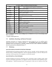
Table 4: Gas Connection Pipe Sizes
(Minimum incoming pipe size should be 1-1/2" (38 mm))
Natural 3/4" (19 mm) 1" (25 mm) 1-1/4" (33 mm)
Propane 1/2" (13 mm) 3/4" (19 mm) 1" (25 mm)
Manufactured 1" (25 mm) 1-1/4" (33 mm) 1-1/2" (38 mm)
* For distances of more than 20 feet (6 meters)
and/or more than four fittings or elbows, increase
the connection by one pipe size.
Gas Single Unit 2 - 3 Units 4 Units*
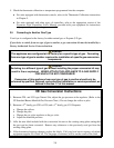
CE Standard
CE regulations require a combustion air supply of 2m
3
/h per kW per fryer. (See rating plate affixed
to door for kW rating.)
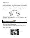
1. Connect the quick-disconnect hose to the fryer quick-disconnect fitting under the front of the
fryer and to the building gas line.
NOTE: Some fryers are configured for a rigid connection to the gas supply line. These units are
connected to the gas supply line at the rear of the unit.
When using thread compound, use very small amounts on male threads only. Use a pipe thread
compound that is not affected by the chemical action of LP gases (Loctite PST567 sealant is one
such compound). DO NOT apply compound to the first two threads. Applying compound to the
first two threads will cause clogging of the burner orifices and control valve.