3
■ EMULATOR INTERFACE CONNECTOR footprint design notes
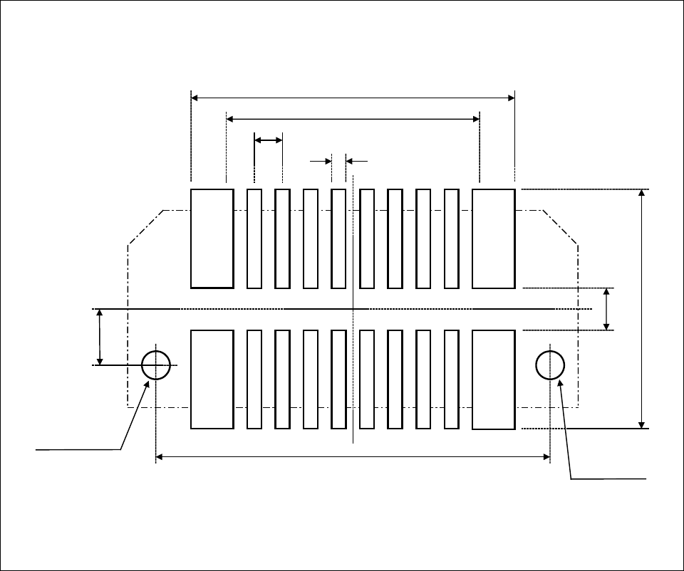
Figure 2 shows the recommended dimensions of the Emulator interface connector footprint mounted
on the PC board of the user system.
The PC board of the user system must be designed with due consideration given to this footprint.
For more information, contact the Tokyo Eletech Corporation.
Figure 2 Recommended Dimensions of the Footprint for Mounting the EMULATOR INTERFACECONNECTOR
φ0.8 0 mm
+ 0.1
φ0.8 0 mm
+ 0.1
5.75 mm
4.5 mm
0.25 mm
2.0 mm
6.0 mm
0.5 mm
1.4 mm
7.1 mm
Positioning hole
*
Positioning hole
*
*:The positioning hole (two places) of a connector is prepared on a PC board.


